
TriStar Manual


28
Installation
{
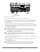
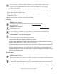
Solar +
Battery +
Solar -
Battery -
(Common Negative)
Figure 3-7. Power terminal locations
Connectthefour(4)powerconductorsshowningure3-7aboveinthefollowingsteps:
1. Conrmthatthesysteminputandoutputdisconnectswitchesarebothturnedoffbefore
connecting the power wires to the controller. There are no disconnect switches inside the
TriStar MPPT 150V.
2. Provide for strain relief if the bottom knockouts are used and conduit is not used.
3. Pull the wires into the wiring box. The Remote Temperature Sensor and Battery Sense wires
can be inside the conduit with the power conductors. It is easier to pull the RTS and Sense
wires before the power cables.
WARNING: Risk of Damage
Be very certain that the battery connection is made with correct polarity. Turn on the battery
breaker/disconnect and measure the voltage on the open battery wires BEFORE connecting to
the TriStar MPPT 150V. Disconnect the battery breaker/disconnect before wiring to the controller.
AVERTISSEMENT : Risque d’endommagement
Assurez-vous que la connexion a la batterie est effectuée avec la polarité correcte. Activez le
coupe-circuit/interrupteur de la batterie et mesure la tension sur les câbles ouverts AVANT la
connexion au TriStar MPPT 150V. Déconnectez le coupe-circuit/interrupteur de la batterie avant
le câblage sur le contrôleur.
4. Connect the Battery + (positive) wire to the Battery + terminal on the TriStar MPPT 150V. The
Battery + terminal has a red cover.
5. Connect the Battery - (negative) wire to one of the Common Negative terminals on the
TriStar MPPT 150V.
WARNING: Risk of Damage
Be very certain that the solar connection is made with correct polarity. Turn on the solar array
breaker/disconnect and measure the voltage on the open wires BEFORE connecting to the
TriStar MPPT 150V. Disconnect the solar breaker/disconnect before wiring to the controller.