
TriStar MPPT as an EIA-485 Network Bridge


page 6 of 8485 Bridging
© 2011 Morningstar Corporation. All rights reserved.
page 6 of 8 Revision Date: 12/22/11
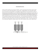
ConnecƟ ng to Remaining Controllers
Bridged communica on on the 485 network requires both physical and so ware connec ons be made with
each controller manually. The sequence in which these connec ons are made does play a role in ensuring
reliable communica on. Begin by removing all power from the bus and controllers. This is a cri cal step as
physically connec ng wire/cable to controllers during normal opera ons has been shown to result in commu-
nica on errors. Once power has been removed, connect all wire/cable to the controllers/adapters. Ensure TS-
MPPT-60 confi gured to bridge communica ons had been connected to both the bus and LAN/WAN. Restore
power to all devices and observe proper LED indica ons (if equipped).
Once all equipment has been physically connected to the 485 bus, so ware(MS View) connec ons must be
established to allow for bridged communica ons. To begin, the user must fi rst establish communica ons with
the Bridge Enabled Master/TS-MPPT-60. Once connected to the Master controller, the IP address may be
verifi ed by viewing the Connec on tab within Device Proper es. Each subsequent device must be manually
added and connected to the network using the procedure listed below:
1: In MS View, select Devices => Manual Connec on.
2. Highlight the device to be connected and click OK. This will open Device Proper es page.
3. Change Connec on Type to “Remote (TCP)” on the Connec on Tab on the Device Proper es Page
4. Enter the IP address the TS-MPPT-60 confi gured as the Modbus/IP Bridge
5. Enter the controller Modbus ID in the “Control Address” fi eld and click OK
*the Controller should now be displayed in the MS View Device pane.
6. Right-click the controller and click Connect.
Note: The Morningstar Relay Driver has a default Modbus ID of 9.