
User's Guide

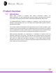
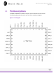
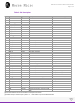
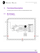
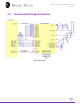
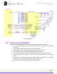
Table Of Contents
- UM P.10 有trace 設計
- 天線trace
- PCB Prints
- MMECH06.PcbDoc
- Top Layer
- Components
- Nets
- 5V_USB
- CC1
- CC2
- GND
- C1-2
- C2-2
- C3-2
- C4-1
- C5-2
- C6-2
- C7-2
- C8-2
- C11-2
- C12-2
- C13-2
- C14-2
- C15-2
- C16-2
- D1-K
- D2-K
- D3-K
- H1-2
- H3-2
- H4-6
- H4-9
- H4-14
- H4-20
- H4-25
- H4-30
- H4-34
- H4-39
- H5-2
- H5-3
- H7-2
- J1-A1
- J1-A12
- J1-B1
- J1-B12
- J1-SH1
- J1-SH2
- J1-SH3
- J1-SH4
- J2-3
- J2-4
- J2-7
- J2-8
- R4-2
- R5-2
- R6-2
- R7-2
- R8-2
- R9-2
- R10-2
- R11-2
- R12-2
- R13-2
- R14-2
- R15-2
- R16-2
- R18-2
- R20-2
- R24-2
- R51-2
- R53-2
- R58-2
- R59-2
- R60-2
- R63-2
- TP1-1
- TP6-1
- TP7-1
- U1-1
- U1-2
- U1-3
- U1-4
- U2-1
- U2-2
- U2-3
- U2-12
- U2-20
- U2-26
- U2-31
- U2-37
- U3-6
- U3-EP
- U4-6
- U4-EP
- VS1-A
- MM_GPIO0
- MM_GPIO1
- MM_GPIO2
- MM_GPIO3
- MM_GPIO4
- MM_GPIO5
- MM_GPIO6
- MM_GPIO7
- MM_GPIO8
- MM_GPIO9
- MM_GPIO10
- MM_GPIO11
- MM_JTAG_TCK
- MM_JTAG_TDI
- MM_JTAG_TDO
- MM_JTAG_TMS
- MM_JTAG_TRST
- MM_RESET_N
- MM_SD_CLK
- MM_SD_CMD
- MM_SD_D0
- MM_SD_D1
- MM_SD_D2
- MM_SD_D3
- MM_WAKE
- NC
- NetC9_2
- NetC10_2
- NetC13_1
- NetC15_1
- NetD1_A
- NetD2_A
- NetD3_A
- NetH5_1
- NetH7_1
- NetR26_2
- NetR27_2
- NetR57_1
- NetR57_2
- Pi_GPIO0
- Pi_GPIO1
- Pi_GPIO2
- Pi_GPIO3
- Pi_GPIO4
- Pi_GPIO5
- Pi_GPIO6
- Pi_GPIO7
- Pi_GPIO8
- Pi_GPIO9
- Pi_GPIO10
- Pi_GPIO11
- Pi_GPIO12
- Pi_GPIO13
- Pi_GPIO14
- Pi_GPIO15
- Pi_GPIO16
- Pi_GPIO17
- Pi_GPIO18
- Pi_GPIO19
- Pi_GPIO20
- Pi_GPIO21
- Pi_GPIO22
- Pi_GPIO23
- Pi_GPIO24
- Pi_GPIO25
- Pi_GPIO26
- Pi_GPIO27
- RPI_ID_WP
- VBAT
- VDD5
- VDD5_RPi
- VDD_3V3
- VDD_3V3_FEM
- VDD_3V3_REG2
- VDD_FEM
- VDDIO
- VDDIO_RAPI
- VFEM_MM
- Ground Plane
- Components
- Nets
- 5V_USB
- CC1
- CC2
- GND
- C1-2
- C2-2
- C3-2
- C4-1
- C5-2
- C6-2
- C7-2
- C8-2
- C11-2
- C12-2
- C13-2
- C14-2
- C15-2
- C16-2
- D1-K
- D2-K
- D3-K
- H1-2
- H3-2
- H4-6
- H4-9
- H4-14
- H4-20
- H4-25
- H4-30
- H4-34
- H4-39
- H5-2
- H5-3
- H7-2
- J1-A1
- J1-A12
- J1-B1
- J1-B12
- J1-SH1
- J1-SH2
- J1-SH3
- J1-SH4
- J2-3
- J2-4
- J2-7
- J2-8
- R4-2
- R5-2
- R6-2
- R7-2
- R8-2
- R9-2
- R10-2
- R11-2
- R12-2
- R13-2
- R14-2
- R15-2
- R16-2
- R18-2
- R20-2
- R24-2
- R51-2
- R53-2
- R58-2
- R59-2
- R60-2
- R63-2
- TP1-1
- TP6-1
- TP7-1
- U1-1
- U1-2
- U1-3
- U1-4
- U2-1
- U2-2
- U2-3
- U2-12
- U2-20
- U2-26
- U2-31
- U2-37
- U3-6
- U3-EP
- U4-6
- U4-EP
- VS1-A
- MM_GPIO0
- MM_GPIO1
- MM_GPIO2
- MM_GPIO3
- MM_GPIO4
- MM_GPIO5
- MM_GPIO6
- MM_GPIO7
- MM_GPIO8
- MM_GPIO9
- MM_GPIO10
- MM_GPIO11
- MM_JTAG_TCK
- MM_JTAG_TDI
- MM_JTAG_TDO
- MM_JTAG_TMS
- MM_JTAG_TRST
- MM_RESET_N
- MM_SD_CLK
- MM_SD_CMD
- MM_SD_D0
- MM_SD_D1
- MM_SD_D2
- MM_SD_D3
- MM_WAKE
- NC
- NetC9_2
- NetC10_2
- NetC13_1
- NetC15_1
- NetD1_A
- NetD2_A
- NetD3_A
- NetH5_1
- NetH7_1
- NetR26_2
- NetR27_2
- NetR57_1
- NetR57_2
- Pi_GPIO0
- Pi_GPIO1
- Pi_GPIO2
- Pi_GPIO3
- Pi_GPIO4
- Pi_GPIO5
- Pi_GPIO6
- Pi_GPIO7
- Pi_GPIO8
- Pi_GPIO9
- Pi_GPIO10
- Pi_GPIO11
- Pi_GPIO12
- Pi_GPIO13
- Pi_GPIO14
- Pi_GPIO15
- Pi_GPIO16
- Pi_GPIO17
- Pi_GPIO18
- Pi_GPIO19
- Pi_GPIO20
- Pi_GPIO21
- Pi_GPIO22
- Pi_GPIO23
- Pi_GPIO24
- Pi_GPIO25
- Pi_GPIO26
- Pi_GPIO27
- RPI_ID_WP
- VBAT
- VDD5
- VDD5_RPi
- VDD_3V3
- VDD_3V3_FEM
- VDD_3V3_REG2
- VDD_FEM
- VDDIO
- VDDIO_RAPI
- VFEM_MM
- Mid Layer 1
- Components
- Nets
- 5V_USB
- CC1
- CC2
- GND
- C1-2
- C2-2
- C3-2
- C4-1
- C5-2
- C6-2
- C7-2
- C8-2
- C11-2
- C12-2
- C13-2
- C14-2
- C15-2
- C16-2
- D1-K
- D2-K
- D3-K
- H1-2
- H3-2
- H4-6
- H4-9
- H4-14
- H4-20
- H4-25
- H4-30
- H4-34
- H4-39
- H5-2
- H5-3
- H7-2
- J1-A1
- J1-A12
- J1-B1
- J1-B12
- J1-SH1
- J1-SH2
- J1-SH3
- J1-SH4
- J2-3
- J2-4
- J2-7
- J2-8
- R4-2
- R5-2
- R6-2
- R7-2
- R8-2
- R9-2
- R10-2
- R11-2
- R12-2
- R13-2
- R14-2
- R15-2
- R16-2
- R18-2
- R20-2
- R24-2
- R51-2
- R53-2
- R58-2
- R59-2
- R60-2
- R63-2
- TP1-1
- TP6-1
- TP7-1
- U1-1
- U1-2
- U1-3
- U1-4
- U2-1
- U2-2
- U2-3
- U2-12
- U2-20
- U2-26
- U2-31
- U2-37
- U3-6
- U3-EP
- U4-6
- U4-EP
- VS1-A
- MM_GPIO0
- MM_GPIO1
- MM_GPIO2
- MM_GPIO3
- MM_GPIO4
- MM_GPIO5
- MM_GPIO6
- MM_GPIO7
- MM_GPIO8
- MM_GPIO9
- MM_GPIO10
- MM_GPIO11
- MM_JTAG_TCK
- MM_JTAG_TDI
- MM_JTAG_TDO
- MM_JTAG_TMS
- MM_JTAG_TRST
- MM_RESET_N
- MM_SD_CLK
- MM_SD_CMD
- MM_SD_D0
- MM_SD_D1
- MM_SD_D2
- MM_SD_D3
- MM_WAKE
- NC
- NetC9_2
- NetC10_2
- NetC13_1
- NetC15_1
- NetD1_A
- NetD2_A
- NetD3_A
- NetH5_1
- NetH7_1
- NetR26_2
- NetR27_2
- NetR57_1
- NetR57_2
- Pi_GPIO0
- Pi_GPIO1
- Pi_GPIO2
- Pi_GPIO3
- Pi_GPIO4
- Pi_GPIO5
- Pi_GPIO6
- Pi_GPIO7
- Pi_GPIO8
- Pi_GPIO9
- Pi_GPIO10
- Pi_GPIO11
- Pi_GPIO12
- Pi_GPIO13
- Pi_GPIO14
- Pi_GPIO15
- Pi_GPIO16
- Pi_GPIO17
- Pi_GPIO18
- Pi_GPIO19
- Pi_GPIO20
- Pi_GPIO21
- Pi_GPIO22
- Pi_GPIO23
- Pi_GPIO24
- Pi_GPIO25
- Pi_GPIO26
- Pi_GPIO27
- RPI_ID_WP
- VBAT
- VDD5
- VDD5_RPi
- VDD_3V3
- VDD_3V3_FEM
- VDD_3V3_REG2
- VDD_FEM
- VDDIO
- VDDIO_RAPI
- VFEM_MM
- Bottom Layer
- Components
- Nets
- 5V_USB
- CC1
- CC2
- GND
- C1-2
- C2-2
- C3-2
- C4-1
- C5-2
- C6-2
- C7-2
- C8-2
- C11-2
- C12-2
- C13-2
- C14-2
- C15-2
- C16-2
- D1-K
- D2-K
- D3-K
- H1-2
- H3-2
- H4-6
- H4-9
- H4-14
- H4-20
- H4-25
- H4-30
- H4-34
- H4-39
- H5-2
- H5-3
- H7-2
- J1-A1
- J1-A12
- J1-B1
- J1-B12
- J1-SH1
- J1-SH2
- J1-SH3
- J1-SH4
- J2-3
- J2-4
- J2-7
- J2-8
- R4-2
- R5-2
- R6-2
- R7-2
- R8-2
- R9-2
- R10-2
- R11-2
- R12-2
- R13-2
- R14-2
- R15-2
- R16-2
- R18-2
- R20-2
- R24-2
- R51-2
- R53-2
- R58-2
- R59-2
- R60-2
- R63-2
- TP1-1
- TP6-1
- TP7-1
- U1-1
- U1-2
- U1-3
- U1-4
- U2-1
- U2-2
- U2-3
- U2-12
- U2-20
- U2-26
- U2-31
- U2-37
- U3-6
- U3-EP
- U4-6
- U4-EP
- VS1-A
- MM_GPIO0
- MM_GPIO1
- MM_GPIO2
- MM_GPIO3
- MM_GPIO4
- MM_GPIO5
- MM_GPIO6
- MM_GPIO7
- MM_GPIO8
- MM_GPIO9
- MM_GPIO10
- MM_GPIO11
- MM_JTAG_TCK
- MM_JTAG_TDI
- MM_JTAG_TDO
- MM_JTAG_TMS
- MM_JTAG_TRST
- MM_RESET_N
- MM_SD_CLK
- MM_SD_CMD
- MM_SD_D0
- MM_SD_D1
- MM_SD_D2
- MM_SD_D3
- MM_WAKE
- NC
- NetC9_2
- NetC10_2
- NetC13_1
- NetC15_1
- NetD1_A
- NetD2_A
- NetD3_A
- NetH5_1
- NetH7_1
- NetR26_2
- NetR27_2
- NetR57_1
- NetR57_2
- Pi_GPIO0
- Pi_GPIO1
- Pi_GPIO2
- Pi_GPIO3
- Pi_GPIO4
- Pi_GPIO5
- Pi_GPIO6
- Pi_GPIO7
- Pi_GPIO8
- Pi_GPIO9
- Pi_GPIO10
- Pi_GPIO11
- Pi_GPIO12
- Pi_GPIO13
- Pi_GPIO14
- Pi_GPIO15
- Pi_GPIO16
- Pi_GPIO17
- Pi_GPIO18
- Pi_GPIO19
- Pi_GPIO20
- Pi_GPIO21
- Pi_GPIO22
- Pi_GPIO23
- Pi_GPIO24
- Pi_GPIO25
- Pi_GPIO26
- Pi_GPIO27
- RPI_ID_WP
- VBAT
- VDD5
- VDD5_RPi
- VDD_3V3
- VDD_3V3_FEM
- VDD_3V3_REG2
- VDD_FEM
- VDDIO
- VDDIO_RAPI
- VFEM_MM
- Top Silkscreen Overlay
- Components
- Nets
- 5V_USB
- CC1
- CC2
- GND
- C1-2
- C2-2
- C3-2
- C4-1
- C5-2
- C6-2
- C7-2
- C8-2
- C11-2
- C12-2
- C13-2
- C14-2
- C15-2
- C16-2
- D1-K
- D2-K
- D3-K
- H1-2
- H3-2
- H4-6
- H4-9
- H4-14
- H4-20
- H4-25
- H4-30
- H4-34
- H4-39
- H5-2
- H5-3
- H7-2
- J1-A1
- J1-A12
- J1-B1
- J1-B12
- J1-SH1
- J1-SH2
- J1-SH3
- J1-SH4
- J2-3
- J2-4
- J2-7
- J2-8
- R4-2
- R5-2
- R6-2
- R7-2
- R8-2
- R9-2
- R10-2
- R11-2
- R12-2
- R13-2
- R14-2
- R15-2
- R16-2
- R18-2
- R20-2
- R24-2
- R51-2
- R53-2
- R58-2
- R59-2
- R60-2
- R63-2
- TP1-1
- TP6-1
- TP7-1
- U1-1
- U1-2
- U1-3
- U1-4
- U2-1
- U2-2
- U2-3
- U2-12
- U2-20
- U2-26
- U2-31
- U2-37
- U3-6
- U3-EP
- U4-6
- U4-EP
- VS1-A
- MM_GPIO0
- MM_GPIO1
- MM_GPIO2
- MM_GPIO3
- MM_GPIO4
- MM_GPIO5
- MM_GPIO6
- MM_GPIO7
- MM_GPIO8
- MM_GPIO9
- MM_GPIO10
- MM_GPIO11
- MM_JTAG_TCK
- MM_JTAG_TDI
- MM_JTAG_TDO
- MM_JTAG_TMS
- MM_JTAG_TRST
- MM_RESET_N
- MM_SD_CLK
- MM_SD_CMD
- MM_SD_D0
- MM_SD_D1
- MM_SD_D2
- MM_SD_D3
- MM_WAKE
- NC
- NetC9_2
- NetC10_2
- NetC13_1
- NetC15_1
- NetD1_A
- NetD2_A
- NetD3_A
- NetH5_1
- NetH7_1
- NetR26_2
- NetR27_2
- NetR57_1
- NetR57_2
- Pi_GPIO0
- Pi_GPIO1
- Pi_GPIO2
- Pi_GPIO3
- Pi_GPIO4
- Pi_GPIO5
- Pi_GPIO6
- Pi_GPIO7
- Pi_GPIO8
- Pi_GPIO9
- Pi_GPIO10
- Pi_GPIO11
- Pi_GPIO12
- Pi_GPIO13
- Pi_GPIO14
- Pi_GPIO15
- Pi_GPIO16
- Pi_GPIO17
- Pi_GPIO18
- Pi_GPIO19
- Pi_GPIO20
- Pi_GPIO21
- Pi_GPIO22
- Pi_GPIO23
- Pi_GPIO24
- Pi_GPIO25
- Pi_GPIO26
- Pi_GPIO27
- RPI_ID_WP
- VBAT
- VDD5
- VDD5_RPi
- VDD_3V3
- VDD_3V3_FEM
- VDD_3V3_REG2
- VDD_FEM
- VDDIO
- VDDIO_RAPI
- VFEM_MM
- Top Paste Mask Print
- Components
- Nets
- 5V_USB
- CC1
- CC2
- GND
- C1-2
- C2-2
- C3-2
- C4-1
- C5-2
- C6-2
- C7-2
- C8-2
- C11-2
- C12-2
- C13-2
- C14-2
- C15-2
- C16-2
- D1-K
- D2-K
- D3-K
- H1-2
- H3-2
- H4-6
- H4-9
- H4-14
- H4-20
- H4-25
- H4-30
- H4-34
- H4-39
- H5-2
- H5-3
- H7-2
- J1-A1
- J1-A12
- J1-B1
- J1-B12
- J1-SH1
- J1-SH2
- J1-SH3
- J1-SH4
- J2-3
- J2-4
- J2-7
- J2-8
- R4-2
- R5-2
- R6-2
- R7-2
- R8-2
- R9-2
- R10-2
- R11-2
- R12-2
- R13-2
- R14-2
- R15-2
- R16-2
- R18-2
- R20-2
- R24-2
- R51-2
- R53-2
- R58-2
- R59-2
- R60-2
- R63-2
- TP1-1
- TP6-1
- TP7-1
- U1-1
- U1-2
- U1-3
- U1-4
- U2-1
- U2-2
- U2-3
- U2-12
- U2-20
- U2-26
- U2-31
- U2-37
- U3-6
- U3-EP
- U4-6
- U4-EP
- VS1-A
- MM_GPIO0
- MM_GPIO1
- MM_GPIO2
- MM_GPIO3
- MM_GPIO4
- MM_GPIO5
- MM_GPIO6
- MM_GPIO7
- MM_GPIO8
- MM_GPIO9
- MM_GPIO10
- MM_GPIO11
- MM_JTAG_TCK
- MM_JTAG_TDI
- MM_JTAG_TDO
- MM_JTAG_TMS
- MM_JTAG_TRST
- MM_RESET_N
- MM_SD_CLK
- MM_SD_CMD
- MM_SD_D0
- MM_SD_D1
- MM_SD_D2
- MM_SD_D3
- MM_WAKE
- NC
- NetC9_2
- NetC10_2
- NetC13_1
- NetC15_1
- NetD1_A
- NetD2_A
- NetD3_A
- NetH5_1
- NetH7_1
- NetR26_2
- NetR27_2
- NetR57_1
- NetR57_2
- Pi_GPIO0
- Pi_GPIO1
- Pi_GPIO2
- Pi_GPIO3
- Pi_GPIO4
- Pi_GPIO5
- Pi_GPIO6
- Pi_GPIO7
- Pi_GPIO8
- Pi_GPIO9
- Pi_GPIO10
- Pi_GPIO11
- Pi_GPIO12
- Pi_GPIO13
- Pi_GPIO14
- Pi_GPIO15
- Pi_GPIO16
- Pi_GPIO17
- Pi_GPIO18
- Pi_GPIO19
- Pi_GPIO20
- Pi_GPIO21
- Pi_GPIO22
- Pi_GPIO23
- Pi_GPIO24
- Pi_GPIO25
- Pi_GPIO26
- Pi_GPIO27
- RPI_ID_WP
- VBAT
- VDD5
- VDD5_RPi
- VDD_3V3
- VDD_3V3_FEM
- VDD_3V3_REG2
- VDD_FEM
- VDDIO
- VDDIO_RAPI
- VFEM_MM
- Top Solder Mask Print
- Components
- Nets
- 5V_USB
- CC1
- CC2
- GND
- C1-2
- C2-2
- C3-2
- C4-1
- C5-2
- C6-2
- C7-2
- C8-2
- C11-2
- C12-2
- C13-2
- C14-2
- C15-2
- C16-2
- D1-K
- D2-K
- D3-K
- H1-2
- H3-2
- H4-6
- H4-9
- H4-14
- H4-20
- H4-25
- H4-30
- H4-34
- H4-39
- H5-2
- H5-3
- H7-2
- J1-A1
- J1-A12
- J1-B1
- J1-B12
- J1-SH1
- J1-SH2
- J1-SH3
- J1-SH4
- J2-3
- J2-4
- J2-7
- J2-8
- R4-2
- R5-2
- R6-2
- R7-2
- R8-2
- R9-2
- R10-2
- R11-2
- R12-2
- R13-2
- R14-2
- R15-2
- R16-2
- R18-2
- R20-2
- R24-2
- R51-2
- R53-2
- R58-2
- R59-2
- R60-2
- R63-2
- TP1-1
- TP6-1
- TP7-1
- U1-1
- U1-2
- U1-3
- U1-4
- U2-1
- U2-2
- U2-3
- U2-12
- U2-20
- U2-26
- U2-31
- U2-37
- U3-6
- U3-EP
- U4-6
- U4-EP
- VS1-A
- MM_GPIO0
- MM_GPIO1
- MM_GPIO2
- MM_GPIO3
- MM_GPIO4
- MM_GPIO5
- MM_GPIO6
- MM_GPIO7
- MM_GPIO8
- MM_GPIO9
- MM_GPIO10
- MM_GPIO11
- MM_JTAG_TCK
- MM_JTAG_TDI
- MM_JTAG_TDO
- MM_JTAG_TMS
- MM_JTAG_TRST
- MM_RESET_N
- MM_SD_CLK
- MM_SD_CMD
- MM_SD_D0
- MM_SD_D1
- MM_SD_D2
- MM_SD_D3
- MM_WAKE
- NC
- NetC9_2
- NetC10_2
- NetC13_1
- NetC15_1
- NetD1_A
- NetD2_A
- NetD3_A
- NetH5_1
- NetH7_1
- NetR26_2
- NetR27_2
- NetR57_1
- NetR57_2
- Pi_GPIO0
- Pi_GPIO1
- Pi_GPIO2
- Pi_GPIO3
- Pi_GPIO4
- Pi_GPIO5
- Pi_GPIO6
- Pi_GPIO7
- Pi_GPIO8
- Pi_GPIO9
- Pi_GPIO10
- Pi_GPIO11
- Pi_GPIO12
- Pi_GPIO13
- Pi_GPIO14
- Pi_GPIO15
- Pi_GPIO16
- Pi_GPIO17
- Pi_GPIO18
- Pi_GPIO19
- Pi_GPIO20
- Pi_GPIO21
- Pi_GPIO22
- Pi_GPIO23
- Pi_GPIO24
- Pi_GPIO25
- Pi_GPIO26
- Pi_GPIO27
- RPI_ID_WP
- VBAT
- VDD5
- VDD5_RPi
- VDD_3V3
- VDD_3V3_FEM
- VDD_3V3_REG2
- VDD_FEM
- VDDIO
- VDDIO_RAPI
- VFEM_MM
- Bottom Solder Mask Print
- Components
- Nets
- 5V_USB
- CC1
- CC2
- GND
- C1-2
- C2-2
- C3-2
- C4-1
- C5-2
- C6-2
- C7-2
- C8-2
- C11-2
- C12-2
- C13-2
- C14-2
- C15-2
- C16-2
- D1-K
- D2-K
- D3-K
- H1-2
- H3-2
- H4-6
- H4-9
- H4-14
- H4-20
- H4-25
- H4-30
- H4-34
- H4-39
- H5-2
- H5-3
- H7-2
- J1-A1
- J1-A12
- J1-B1
- J1-B12
- J1-SH1
- J1-SH2
- J1-SH3
- J1-SH4
- J2-3
- J2-4
- J2-7
- J2-8
- R4-2
- R5-2
- R6-2
- R7-2
- R8-2
- R9-2
- R10-2
- R11-2
- R12-2
- R13-2
- R14-2
- R15-2
- R16-2
- R18-2
- R20-2
- R24-2
- R51-2
- R53-2
- R58-2
- R59-2
- R60-2
- R63-2
- TP1-1
- TP6-1
- TP7-1
- U1-1
- U1-2
- U1-3
- U1-4
- U2-1
- U2-2
- U2-3
- U2-12
- U2-20
- U2-26
- U2-31
- U2-37
- U3-6
- U3-EP
- U4-6
- U4-EP
- VS1-A
- MM_GPIO0
- MM_GPIO1
- MM_GPIO2
- MM_GPIO3
- MM_GPIO4
- MM_GPIO5
- MM_GPIO6
- MM_GPIO7
- MM_GPIO8
- MM_GPIO9
- MM_GPIO10
- MM_GPIO11
- MM_JTAG_TCK
- MM_JTAG_TDI
- MM_JTAG_TDO
- MM_JTAG_TMS
- MM_JTAG_TRST
- MM_RESET_N
- MM_SD_CLK
- MM_SD_CMD
- MM_SD_D0
- MM_SD_D1
- MM_SD_D2
- MM_SD_D3
- MM_WAKE
- NC
- NetC9_2
- NetC10_2
- NetC13_1
- NetC15_1
- NetD1_A
- NetD2_A
- NetD3_A
- NetH5_1
- NetH7_1
- NetR26_2
- NetR27_2
- NetR57_1
- NetR57_2
- Pi_GPIO0
- Pi_GPIO1
- Pi_GPIO2
- Pi_GPIO3
- Pi_GPIO4
- Pi_GPIO5
- Pi_GPIO6
- Pi_GPIO7
- Pi_GPIO8
- Pi_GPIO9
- Pi_GPIO10
- Pi_GPIO11
- Pi_GPIO12
- Pi_GPIO13
- Pi_GPIO14
- Pi_GPIO15
- Pi_GPIO16
- Pi_GPIO17
- Pi_GPIO18
- Pi_GPIO19
- Pi_GPIO20
- Pi_GPIO21
- Pi_GPIO22
- Pi_GPIO23
- Pi_GPIO24
- Pi_GPIO25
- Pi_GPIO26
- Pi_GPIO27
- RPI_ID_WP
- VBAT
- VDD5
- VDD5_RPi
- VDD_3V3
- VDD_3V3_FEM
- VDD_3V3_REG2
- VDD_FEM
- VDDIO
- VDDIO_RAPI
- VFEM_MM
- Drill Drawing For (Top Layer - Bottom Layer)
- Components
- Nets
- 5V_USB
- CC1
- CC2
- GND
- C1-2
- C2-2
- C3-2
- C4-1
- C5-2
- C6-2
- C7-2
- C8-2
- C11-2
- C12-2
- C13-2
- C14-2
- C15-2
- C16-2
- D1-K
- D2-K
- D3-K
- H1-2
- H3-2
- H4-6
- H4-9
- H4-14
- H4-20
- H4-25
- H4-30
- H4-34
- H4-39
- H5-2
- H5-3
- H7-2
- J1-A1
- J1-A12
- J1-B1
- J1-B12
- J1-SH1
- J1-SH2
- J1-SH3
- J1-SH4
- J2-3
- J2-4
- J2-7
- J2-8
- R4-2
- R5-2
- R6-2
- R7-2
- R8-2
- R9-2
- R10-2
- R11-2
- R12-2
- R13-2
- R14-2
- R15-2
- R16-2
- R18-2
- R20-2
- R24-2
- R51-2
- R53-2
- R58-2
- R59-2
- R60-2
- R63-2
- TP1-1
- TP6-1
- TP7-1
- U1-1
- U1-2
- U1-3
- U1-4
- U2-1
- U2-2
- U2-3
- U2-12
- U2-20
- U2-26
- U2-31
- U2-37
- U3-6
- U3-EP
- U4-6
- U4-EP
- VS1-A
- MM_GPIO0
- MM_GPIO1
- MM_GPIO2
- MM_GPIO3
- MM_GPIO4
- MM_GPIO5
- MM_GPIO6
- MM_GPIO7
- MM_GPIO8
- MM_GPIO9
- MM_GPIO10
- MM_GPIO11
- MM_JTAG_TCK
- MM_JTAG_TDI
- MM_JTAG_TDO
- MM_JTAG_TMS
- MM_JTAG_TRST
- MM_RESET_N
- MM_SD_CLK
- MM_SD_CMD
- MM_SD_D0
- MM_SD_D1
- MM_SD_D2
- MM_SD_D3
- MM_WAKE
- NC
- NetC9_2
- NetC10_2
- NetC13_1
- NetC15_1
- NetD1_A
- NetD2_A
- NetD3_A
- NetH5_1
- NetH7_1
- NetR26_2
- NetR27_2
- NetR57_1
- NetR57_2
- Pi_GPIO0
- Pi_GPIO1
- Pi_GPIO2
- Pi_GPIO3
- Pi_GPIO4
- Pi_GPIO5
- Pi_GPIO6
- Pi_GPIO7
- Pi_GPIO8
- Pi_GPIO9
- Pi_GPIO10
- Pi_GPIO11
- Pi_GPIO12
- Pi_GPIO13
- Pi_GPIO14
- Pi_GPIO15
- Pi_GPIO16
- Pi_GPIO17
- Pi_GPIO18
- Pi_GPIO19
- Pi_GPIO20
- Pi_GPIO21
- Pi_GPIO22
- Pi_GPIO23
- Pi_GPIO24
- Pi_GPIO25
- Pi_GPIO26
- Pi_GPIO27
- RPI_ID_WP
- VBAT
- VDD5
- VDD5_RPi
- VDD_3V3
- VDD_3V3_FEM
- VDD_3V3_REG2
- VDD_FEM
- VDDIO
- VDDIO_RAPI
- VFEM_MM
- Drill Guide For (Top Layer - Bottom Layer)
- Components
- Nets
- 5V_USB
- CC1
- CC2
- GND
- C1-2
- C2-2
- C3-2
- C4-1
- C5-2
- C6-2
- C7-2
- C8-2
- C11-2
- C12-2
- C13-2
- C14-2
- C15-2
- C16-2
- D1-K
- D2-K
- D3-K
- H1-2
- H3-2
- H4-6
- H4-9
- H4-14
- H4-20
- H4-25
- H4-30
- H4-34
- H4-39
- H5-2
- H5-3
- H7-2
- J1-A1
- J1-A12
- J1-B1
- J1-B12
- J1-SH1
- J1-SH2
- J1-SH3
- J1-SH4
- J2-3
- J2-4
- J2-7
- J2-8
- R4-2
- R5-2
- R6-2
- R7-2
- R8-2
- R9-2
- R10-2
- R11-2
- R12-2
- R13-2
- R14-2
- R15-2
- R16-2
- R18-2
- R20-2
- R24-2
- R51-2
- R53-2
- R58-2
- R59-2
- R60-2
- R63-2
- TP1-1
- TP6-1
- TP7-1
- U1-1
- U1-2
- U1-3
- U1-4
- U2-1
- U2-2
- U2-3
- U2-12
- U2-20
- U2-26
- U2-31
- U2-37
- U3-6
- U3-EP
- U4-6
- U4-EP
- VS1-A
- MM_GPIO0
- MM_GPIO1
- MM_GPIO2
- MM_GPIO3
- MM_GPIO4
- MM_GPIO5
- MM_GPIO6
- MM_GPIO7
- MM_GPIO8
- MM_GPIO9
- MM_GPIO10
- MM_GPIO11
- MM_JTAG_TCK
- MM_JTAG_TDI
- MM_JTAG_TDO
- MM_JTAG_TMS
- MM_JTAG_TRST
- MM_RESET_N
- MM_SD_CLK
- MM_SD_CMD
- MM_SD_D0
- MM_SD_D1
- MM_SD_D2
- MM_SD_D3
- MM_WAKE
- NC
- NetC9_2
- NetC10_2
- NetC13_1
- NetC15_1
- NetD1_A
- NetD2_A
- NetD3_A
- NetH5_1
- NetH7_1
- NetR26_2
- NetR27_2
- NetR57_1
- NetR57_2
- Pi_GPIO0
- Pi_GPIO1
- Pi_GPIO2
- Pi_GPIO3
- Pi_GPIO4
- Pi_GPIO5
- Pi_GPIO6
- Pi_GPIO7
- Pi_GPIO8
- Pi_GPIO9
- Pi_GPIO10
- Pi_GPIO11
- Pi_GPIO12
- Pi_GPIO13
- Pi_GPIO14
- Pi_GPIO15
- Pi_GPIO16
- Pi_GPIO17
- Pi_GPIO18
- Pi_GPIO19
- Pi_GPIO20
- Pi_GPIO21
- Pi_GPIO22
- Pi_GPIO23
- Pi_GPIO24
- Pi_GPIO25
- Pi_GPIO26
- Pi_GPIO27
- RPI_ID_WP
- VBAT
- VDD5
- VDD5_RPi
- VDD_3V3
- VDD_3V3_FEM
- VDD_3V3_REG2
- VDD_FEM
- VDDIO
- VDDIO_RAPI
- VFEM_MM
- Top Layer
- MMECH06.PcbDoc
- Fab Prints
- MMECH06.PcbDoc
- Fab
- Components
- Nets
- 5V_USB
- CC1
- CC2
- GND
- C1-2
- C2-2
- C3-2
- C4-1
- C5-2
- C6-2
- C7-2
- C8-2
- C11-2
- C12-2
- C13-2
- C14-2
- C15-2
- C16-2
- D1-K
- D2-K
- D3-K
- H1-2
- H3-2
- H4-6
- H4-9
- H4-14
- H4-20
- H4-25
- H4-30
- H4-34
- H4-39
- H5-2
- H5-3
- H7-2
- J1-A1
- J1-A12
- J1-B1
- J1-B12
- J1-SH1
- J1-SH2
- J1-SH3
- J1-SH4
- J2-3
- J2-4
- J2-7
- J2-8
- R4-2
- R5-2
- R6-2
- R7-2
- R8-2
- R9-2
- R10-2
- R11-2
- R12-2
- R13-2
- R14-2
- R15-2
- R16-2
- R18-2
- R20-2
- R24-2
- R51-2
- R53-2
- R58-2
- R59-2
- R60-2
- R63-2
- TP1-1
- TP6-1
- TP7-1
- U1-1
- U1-2
- U1-3
- U1-4
- U2-1
- U2-2
- U2-3
- U2-12
- U2-20
- U2-26
- U2-31
- U2-37
- U3-6
- U3-EP
- U4-6
- U4-EP
- VS1-A
- MM_GPIO0
- MM_GPIO1
- MM_GPIO2
- MM_GPIO3
- MM_GPIO4
- MM_GPIO5
- MM_GPIO6
- MM_GPIO7
- MM_GPIO8
- MM_GPIO9
- MM_GPIO10
- MM_GPIO11
- MM_JTAG_TCK
- MM_JTAG_TDI
- MM_JTAG_TDO
- MM_JTAG_TMS
- MM_JTAG_TRST
- MM_RESET_N
- MM_SD_CLK
- MM_SD_CMD
- MM_SD_D0
- MM_SD_D1
- MM_SD_D2
- MM_SD_D3
- MM_WAKE
- NC
- NetC9_2
- NetC10_2
- NetC13_1
- NetC15_1
- NetD1_A
- NetD2_A
- NetD3_A
- NetH5_1
- NetH7_1
- NetR26_2
- NetR27_2
- NetR57_1
- NetR57_2
- Pi_GPIO0
- Pi_GPIO1
- Pi_GPIO2
- Pi_GPIO3
- Pi_GPIO4
- Pi_GPIO5
- Pi_GPIO6
- Pi_GPIO7
- Pi_GPIO8
- Pi_GPIO9
- Pi_GPIO10
- Pi_GPIO11
- Pi_GPIO12
- Pi_GPIO13
- Pi_GPIO14
- Pi_GPIO15
- Pi_GPIO16
- Pi_GPIO17
- Pi_GPIO18
- Pi_GPIO19
- Pi_GPIO20
- Pi_GPIO21
- Pi_GPIO22
- Pi_GPIO23
- Pi_GPIO24
- Pi_GPIO25
- Pi_GPIO26
- Pi_GPIO27
- RPI_ID_WP
- VBAT
- VDD5
- VDD5_RPi
- VDD_3V3
- VDD_3V3_FEM
- VDD_3V3_REG2
- VDD_FEM
- VDDIO
- VDDIO_RAPI
- VFEM_MM
- Fab
- MMECH06.PcbDoc
- Draftsman
- PCB Prints
- FCC statement

MM6108-MF08251 User Guide UG100
IEEE 802.11ah Sub-1G Wi-Fi HaLow Module
Page 10/19
SPI Configuration
3.3. General Layout Guidelines
In order to achieve optimal RF performance, the following steps should be followed:
1. Use a 50Ω impedance controlled trace from the antenna pin (38) and the antenna
connection.
2. Use a solid ground plane under the RF trace and the module.
3. Ensure the ground fill is heavily stitched with vias round the RF traces.
4. Keep all power supply and digital signals away from the RF traces.
5. If an impedance matching circuit is needed, ensure that no RF stubs are created.
6. Keep the RF path short, smooth and near. Use large radius bends, never 90 degree
bends.
7. Choose a pcb stackup so the RF trace width is close to the width of the matching
component pads. This will minimize any impedance mismatch.
8. Do not use thermals on RF traces because of their high loss.