Model M45C How to install, operate and maintain your Demand Controlled Water Softener with Wi-Fi Do not return water softener to store If you have any questions or concerns when installing, operating or maintaining your water softener, call our toll free number: 1-888-64 WATER (1-888-649-2837) or visit www.mortonwatersofteners.com When you call, please be prepared to provide the model and serial number of your product, found on the rating decal, located on the rim below the salt lid hinges.
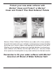
Protect your new water softener with Morton® Clean and Protect® or Morton® Clean and Protect® Plus Rust Defense® Pellets Morton ® Water Softener Salt Pellets are made with a time-release formula that works with your softener to help prevent mineral buildup and keep your home’s pipes and appliances working at their best. Whether you’re looking to remove iron and fight buildup, or extend your water softener’s life, Morton® has the right salt for you.
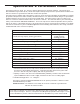
TABLE OF CONTENTS Page Inspect Shipment . . . . . . . . . . . . . . . . . . . . . . . . . . . . . . . . . . . . . . . . . . . . . . . . . . . . . . . . . . . . . . . . . . . . . . . . . . . . 4 Dimensions . . . . . . . . . . . . . . . . . . . . . . . . . . . . . . . . . . . . . . . . . . . . . . . . . . . . . . . . . . . . . . . . . . . . . . . . . . . . . . . . 4 Specifications & Performance Claims . . . . . . . . . . . . . . . . . . . . . . . . . . . . . . . . . . . . . . . . . . . . . . . . . . . . . .
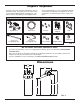
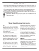
Inspect Shipment The parts required to assemble and install the unit are included in a bag. Thoroughly check the water softener for possible shipping damage and parts loss. Also inspect and note any damage to the shipping carton. Remove and discard (or recycle) all packing materials. To avoid loss of small parts, we suggest you keep the small parts in the parts bag until you are ready to use them.
Specifications & Performance Claims This model is efficiency rated. The efficiency rating is valid only at the minimum salt dose. This system has a demand initiated regeneration (D.I.R.) feature that complies with specific performance specifications intended to minimize the amount of regenerant brine and water used in their operation.
Before You Start = The water softener requires a minimum water flow of 3 gallons per minute at the inlet. Maximum allowable inlet water pressure is 125 psi. If daytime pressure is over 80 psi, nighttime pressure may exceed the maximum. Use a pressure reducing valve if necessary (Adding a pressure reducing valve may reduce the flow). If your home is equipped with a back flow preventer, an expansion tank must be installed in accordance with local codes and laws.
Installation Requirements Location Requirements Consider all of the following when selecting an installation location for the water softener. = Do not locate the water softener where freezing temperatures occur. Do not attempt to treat water over 120ºF. Freezing temperatures or hot water damage voids the warranty. = To condition all water in the home, install the water softener close to the water supply inlet, and upstream of all other plumbing connections, except outside water pipes.
Installation Requirements Valve Drain Requirements Using the flexible drain hose (included), measure and cut to the length needed. Flexible drain hose is not allowed in all localities (check your plumbing codes). If local codes do not allow use of a flexible drain hose, a rigid valve drain run must be used. Purchase a compression fitting (1/4 NPT x 1/2 in. minimum tube) and 1/2" tubing from your local hardware store. Plumb a rigid drain as needed (See Figure 6).
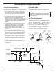
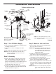
Installation Instructions To Outside Faucets Hard Water TYPICAL INSTALLATION r Pipe Main Wate Soft Water Clips Water Softener Valve To Controller Overflow Drain Elbow Valve Drain Elbow Salt Storage Tank Overflow Hose* Valve Drain Hose* Inlet Lubricated O-ring Secure Valve Drain Hose in place over Floor Drain Floor Drain Step 1. Turn Off Water Supply 1. Close the main water supply valve, located near the well pump or water meter. 2. Shut off the electric or fuel supply to the water heater.
Installation Instructions TYPICAL INSTALLATION (with optional motorized water shutoff valve) To Outside Faucets Hard Water r Pipe Main Wate Soft Water Water Softener Valve Plug into Controller Valve Drain Elbow Valve Drain Hose* *Do not connect the water softener valve drain tubing to the salt storage tank overflow hose.
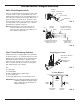
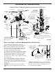
Installation Instructions Step 5. Complete Inlet and Outlet Plumbing Measure, cut, and loosely assemble pipe and fittings from the main water pipe to the inlet and outlet ports of the water softener valve. Be sure to keep fittings fully together, and pipes squared and straight. Be sure hard water supply pipe goes to the water softener valve inlet side. NOTE: Inlet and outlet are marked on the water softener valve. Trace the water flow direction to be sure hard water is to inlet.
Installation Instructions Step 6. Cold Water Pipe Grounding CAUTION: The house cold water pipe (metal only) is often used as a ground for the house electrical system, The 3-valve bypass type of installation, shown in Figure 8, will maintain ground continuity. If you use a plastic bypass valve at the unit, continuity is broken. To restore the ground, do the following: 1.
Installation Instructions continued from previous page bypass valve body toward the softener (See Figure 15). Improper removal may damage clips. Do not reinstall damaged clips. If removing clips... ...depressurize the plumbing, then push Bypass Valve body toward softener FIG. 15 Step 10. Add Water and Salt to the Salt Storage Tank 1. Using a container, add about three gallons of clean water into the salt storage tank. 2.
Programming the Water Softener UP button Display DOWN button SELECT button RECHARGE button CONNECTION STATUS light FIG. 16 Clean Reminder The screen in Figure 17 appears, with “CLEAn” flashing in the display, when four months have elapsed on the system’s timer since start up or the last reset. Program the Softener When the power supply is plugged into the electrical outlet, the model code (o45) and a software version number (example: r4.1), are briefly shown in the faceplate display.
Programming the Water Softener continued from previous page 1. Press the p UP or q DOWN buttons to set the present time. Up moves the display ahead; down sets the time back. Be sure AM or PM is correct. NOTE: Press buttons and quickly release to slowly advance the display. Hold the buttons down for fast advance. NOTE: On Wi-Fi connected systems, the current time will be updated and maintained automatically via Wi-Fi. 2.
Programming the Water Softener Step 5. Set Salt Level If you completed the previous step, the words “SET SALT LEVEL" should show in the display. Otherwise, press the SELECT button until they do. Salt Level 8 7 6 5 4 Sometimes, a manually initiated recharge (regeneration) may be desired, or needed. Two examples are: = = Brinewell You have used more water than usual (guests visiting) and you may run out of soft water before the next automatic regeneration.
Connecting the System to Wi-Fi Step 1. Download the iQua™ App Go to the App Store or Google Play and download the iQua™ app. This must be installed on your phone to set up an account and connect your water softener to the “cloud”. Step 2. Set Up Your Account 1. Activate the iQua™ app. 2. On the welcome screen, click Create an Account. Step 3. Put Water Softener Control into Connect Mode 1. If you haven’t already done so, program the water softener with time, hardness, salt level, etc.
Connecting the System to Wi-Fi Step 4. Connect and Register Your Water Softener 1. If you completed the steps on the previous page, you will have received an account activation e-mail from myiqua.com. Open this e-mail and click on the Activate Account link. 2. Sign in to your account using the e-mail address and password you provided when setting it up. 3. The app screen will change to show Searching for your device... 4. Verify that the softener is still in Connect Mode (flashing amber light).
Controller Features Optional Settings: = Salt Efficiency = Clean Feature = Clean Feature Minutes = Maximum Days Between Regenerations = 97% Feature = 12 / 24 Hour Clock = Backwash & Fast Rinse Times 1. To set any of these options, press and hold the SELECT button for 3 seconds until “000” shows in the display. California Efficiency Requirement Your Morton® Water Softener has a “High Efficiency” feature with an ON or OFF setting.
continued from previous page Controller Features However, you can adjust this time from 1 to 30 minutes in length. To change this cycle time, use the p UP button to increase the time, or the q DOWN button to shorten the time. If no change is desired, continue to next step. 4. Press SELECT again to display the “Recharge Days” screen. FIG. 48 FIG. 50 12 or 24 Hour Clock: All time displays are shown in 12 hour (AM/PM) time format at the default setting.
Power Outage Memory Controller Features If electrical power to the softener is interrupted, the time display is blank, but the electronic controller keeps correct time for several hours. When power is restored, you must reset the present time only if the display is flashing. All other settings are maintained and never require resetting unless a change is desired. If the time is flashing after a long power outage, the softener continues to work as it should to provide you with soft water.
Refilling with Salt Routine Maintenance Lift the salt lid and check the salt storage level frequently. If the water softener uses all the Morton® Clean and Protect™ or Clean and Protect™ Plus Rust Defense™ Pellets before you refill it, you will experience hard water. Until you have established a refilling routine, check the salt every two or three weeks. Always add if less than 1/4 full. Be sure the brinewell cover is on.
Routine Maintenance Cleaning the Nozzle & Venturi A clean nozzle & venturi (See Figure 56) is a necessity for the water softener to work properly. This small component creates the suction to move brine from the brine tank, into the resin tank. If it should become plugged with sand, silt, dirt, etc., the water softener will not work, and hard water will result.
Troubleshooting Automatic Electronic Diagnostics This water softener self-monitors electronic components and circuits for correct operation. If a malfunction occurs, an error code appears in the display. Error Codes 01, 02, 03, 04 & 05: FIG. 58 These are the water softener error codes unrelated to the optional water shutoff valve. While one is in the display, the SELECT button remains operational so the service person can perform the Manual Advance Diagnostics, below, to further isolate the problem.
Troubleshooting Resetting to Factory Defaults To reset the electronic controller to its factory default for all settings (time, hardness, etc.): 1. Press the SELECT button and hold it until the display changes twice to show “CODE” and the flashing model code. 2. Press the p UP button (a few times, if necessary) to display a flashing “SoS”. FIG. 61 3. Press the SELECT button, and the electronic controller will restart. 4. Set the present time, hardness, etc., as described on pages 14-16.
Wiring Schematic Back of Electronic Controller (PWA) 120V AC 60 Hz Power Supply Pwr. In Motor Position/ Turbine Optional Motorized Water Shutoff Valve J6 24V DC Auxiliary Output 24V DC Valve Motor Turbine Sensor OUT GND +5 grn org C NO NC Position Switch Need help troubleshooting? Call Toll Free 1-888-64 WATER (1-888-649-2837) or visit www.mortonwatersofteners.
Optional Motorized Water Shutoff Valve The Motorized Water Shutoff Valve (sold separately) may be used with this Morton® Wi-Fi connected water softener and the iQua™ app to remotely turn off the home’s water supply. For example, you may want to turn off the water when going away on vacation. Install the motorized shutoff valve in the plumbing, upstream of the softener (see page 10), and plug the cable into the softener’s electronic control board with the power off (see page 10 and Figure 63).
Softener Exploded View 1 2 3 Valve Assembly See Pages 30 & 31 for parts 4 5 6 7 29 25 24 30 8 9 11 10 23 12 13 14 26 22 17 18 20 8 7 19 6 27 5 15 16 28 28 21 Morton® Water Softener Installation & Operation Manual
Key No. 1 2 3 4 5 6 ¢ 7 – 8 9 10 Softener Parts List Part No. 7329803 7381504 7351054 7381300 7382403 7372741 7381245 7265025 7112963 á á á 11 7077870 13 0502272 12 14 15 7247996 7105047 7338365 Key No. Description Top Cover Repl. Salt Lid (includes instruction decal & Morton badge) Power Supply, 24V DC Repl. Electronic Control Board (PWA) Heat Shield Faceplate (order decal below) Faceplate Decal Filter Screen O-Ring, 13/16” x 1-1/16” Repl. Resin Tank, 10” x 40” Repl.
Valve Exploded View 102 104 100 103 147 105 146 101 145 109 132 143 141 140 Wear Strip 139 111 Cross-section View 137 148 110 121 112 Seal 138 122 117 118 123 113 136 135 114 127 134 128 116 133 130 129 30 107 108 144 142 131 106 115 119 120 126 125 Morton® Water Softener Installation & Operation Manual 123 124
Key No. Valve Parts List Part No. – 7384691 101 á 100 á 102 7224087 104 0900857 103 105 – 106 107 108 109 110 7231393 7171250 7331169 á á á á á – 7185487 112 á 111 113 114 115 116 á á á á á 117 7174313 – 7342712 118 119 120 7185500 á á 121 7337589 123 7337597 122 124 7342704 7214383 Description Motor, Cam & Gear Kit, 1” (includes Key Nos. 100-102) Motor Cam & Gear Screw, #8-32 x 1” (2 req.) Motor Plate Screw, #6-20 x 3/8” (3 req.
EXTEND YOUR WARRANTY: Use Morton® MWSC Water Softener Cleanser The factory warranty for your water softener is shown below. The one year warranty period, on all parts other than the salt storage tank and fiberglass mineral tank, can be extended to five (5) years from the date of purchase if you use Morton® MWSC Water Softener Cleanser on your system. Use one bottle of Morton® MWSC Water Softener Cleanser, as directed, every four months from the date of purchase of the water softener.