Water Softener Model MSD45E How to install, operate and maintain your Demand Controlled Water Softener Do not return water softener to store If you have questions or concerns when installing, operating or maintaining your water softener, call our toll free number: 1--888--64 WATER (1--888--649--2837) Monday -- Friday 8 AM -- 7 PM EST or visit www.systemsaver.
For best results use Mortonr System Saverr II Pellets to Soften Your Water Mortonr System Saverr II Pellets make a big difference in your water. Mortonr System Saverr II Pellets are specially formulated to consistently outperform other water softening salts in all water softeners. System Saverr II Pellets enable your water softener to remove almost twice as much dirt and impurities and up to 5% more minerals from your water than plain salt pellets.
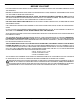
TABLE OF CONTENTS PAGE NO. WARRANTY . . . . . . . . . . . . . . . . . . . . . . . . . . . . . . . . . . . . . . . . . . . . . . . . . . . . . . . . . . . . . . . . . . . . . . . . BEFORE YOU START . . . . . . . . . . . . . . . . . . . . . . . . . . . . . . . . . . . . . . . . . . . . . . . . . . . . . . . . . . . . . . . UNPACKING / INSPECTION . . . . . . . . . . . . . . . . . . . . . . . . . . . . . . . . . . . . . . . . . . . . . . . . . . . . . . . . . SPECIFICATIONS / DIMENSIONS . . . . . . . . . . . .
BEFORE YOU START FOLLOW THE INSTALLATION INSTRUCTIONS CAREFULLY. FAILURE TO INSTALL THE SOFTENER PROPERLY VOIDS THE WARRANTY. BEFORE YOU BEGIN INSTALLATION, READ THIS ENTIRE MANUAL. THEN, OBTAIN ALL THE MATERIALS AND TOOLS YOU WILL NEED TO MAKE THE INSTALLATION. CHECK LOCAL PLUMBING AND ELECTRICAL CODES. THE INSTALLATION MUST CONFORM TO THEM. CODES IN THE STATE OF MASSACHUSETTS REQUIRE INSTALLATION BY A LICENSED PLUMBER. FOR INSTALLATION, USE PLUMBING CODE 248--CMR OF THE COMMONWEALTH OF MASSACHUSETTS.
UNPACKING / INSPECTION The parts required to assemble and install the unit are included in a bag. Thoroughly check the water softener for possible shipping damage and parts loss. Also note damage to the shipping cartons. Remove and discard (or recycle) all packing materials. To avoid loss of the small parts, we suggest you keep them in the parts bag until you are ready to use them. 1 spare clip included Do not return the water softener to store.
SPECIFICATIONS / DIMENSIONS MSD45E 13,300 @ 2.6 35,700 @ 9.9 45,400 @ 17.2 RATED EFFICIENCY (grains / lb @ min. salt dose) H 5120 @ 2.6 AMOUNT OF HIGH CAPACITY RESIN (lbs / cu ft) 65.5 / 1.26 RESIN TANK NOMINAL SIZE (in., dia x height) SERVICE FLOW RATE (gpm) INLET -- OUTLET 11 INTERMITTENT FLOW RATE @ 15 psi (gpm) Y 12.3 WATER SUPPLY MAXIMUM HARDNESS (gpg) 120 WATER SUPPLY MAX. CLEAR WATER IRON (ppm) D 12 WATER PRESSURE LIMITS (min. / max.
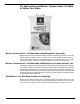
BEFORE STARTING INSTALLATION " WHERE TO INSTALL THE SOFTENER . . . . . . . . . . . . . . . . . . . . . . . . . . . . . . . . . . . . . . . . . . . . . . . . Place the softener as close as possible to the pressure tank (well system) or water meter (city water). Place the softener as close as possible to a floor drain, or other acceptable drain point (laundry tub, sump, standpipe, etc.). Connect the softener to the main water supply pipe BEFORE or AHEAD OF the water heater.
TYPICAL SOLDERED COPPER or CPVC INSTALLATIONS soft water CROSS -- OVER Use if water supply flows from the left. Include single or 3 -- valve bypass.
INSTALLATION STEPS 1. INSTALL BYPASS VALVE and/or PLASTIC INSTALLATION ADAPTORS: NOTE: Before installing the bypass valve or plastic installation adaptors, be sure the turbine and support are firmly in place, in the valve outlet. Blow into the valve port and observe the turbine for free rotation.
INSTALLATION STEPS, continued " If making a soldered copper installation, do all sweat soldering before connecting pipes to the softener fittings. Torch heat will damage plastic parts. " When turning threaded pipe fittings onto plastic fittings, use care not to cross--thread. " Use pipe joint compound on all external pipe threads. " Support inlet and outlet plumbing in some manner (use pipe hangers) to keep the weight off of the valve fittings. 5.
INSTALLATION STEPS, continued 7. CONNECT AND RUN THE BRINE TANK OVERFLOW HOSE: This drain is for safety only. If the brine tank should over--fill with water, the excess is carried to the drain. " Attach a length of flexible hose (included) to the drain elbow, installed in step 2, page 9. Use a hose clamp to hold it in place. " Locate the other end of the hose at the drain point. Do not elevate this hose higher than the elbow on the brine tank. Do not tee this hose to the valve drain hose. 8.
PROGRAMMING THE MORTON WATER SOFTENER RECHARGE button display up button down button Water Softener DATA button " ELECTRONIC CONTROL SETTINGS REQUIRED...upon installation, and after an extended power outage (see Program Memory, page 18). NOTES: D WHEN THE TRANSFORMER IS PLUGGED INTO THE ELECTRICAL OUTLET (STEP 10, PAGE 11), 12:00PM (flashing), and PRESENT TIME show in the upper display area. Program the electronic control as follows. If A - - - is flashing, please see Model Code setting on page 20.
PROGRAMMING THE MORTON WATER SOFTENER, continued " SET WATER HARDNESS NUMBER . . . . . . . . . . . . . . . . . . . . . . . . . . . . . . . . . . . . . . . . . . . . . . . . . . . NOTE: If 25 (factory default) and HARDNESS do not show in the display, press the SELECT button until they do. 1. Press either the SELECT, UP or DOWN button to set your water hardness number in the display. You can get the grains per galThe DOWN button moves the display down to 1.
WATER AND WATER CONDITIONING WATER CONDITIONING INFORMATION . . . . . . . . . . . . . . . . . . . . . . . . . . . . . . . . . . . . . . . . . . . . . . . . . IRON in water can cause stains on clothing and plumbing fixtures. It can negatively affect the taste of food, drinking water, and other beverages. Iron in water is measured in parts per million (ppm). The total* ppm of iron, and type or types*, is determined by chemical analysis.
GENERAL WATER SOFTENER MAINTENANCE CHECKING THE SALT STORAGE LEVEL, AND ADDING SALT (also see page 11) . . . . . . . . . . Brine (salt dissolved in water) is needed for each and every regeneration. The water for making brine is metered into the salt storage area by the softener valve and electronic control. However, you must maintain a level of salt in the tank. In humid areas, it is best to add less salt, more often.
GENERAL WATER SOFTENER MAINTENANCE, continued CLEANING THE NOZZLE AND VENTURI ASSEMBLY . . . . . . . . . . . . . . . . . . . . . . . . . . . . . . . . . . . . . A clean nozzle and venturi is needed for the softener to work right. This small unit makes the suction to move brine from the salt storage area to the resin tank during regeneration. If the nozzle and venturi becomes plugged with sand, silt, dirt, etc., the softener will not work and you will get hard water.
MORTON WATER SOFTENER FEATURES AND SETTINGS NOTE: SEE PAGES 12 and 13 TO SET THE CORRECT TIME OF DAY AND WATER HARDNESS NUMBER. NORMAL OPERATION, ELECTRONIC CONTROL DISPLAY . . . . . . . . . . . . . . . . . . . . . . . . . . . . . . . During normal operation, the present time of day, and AM or PM, show in the time display area. The demand computer determines when a regeneration is needed.
MORTON WATER SOFTENER FEATURES AND SETTINGS, continued RECHARGE NOW Press and hold in the RECHARGE button until RECHARGE NOW starts to flash in the time display area. The softener begins an immediate regeneration, and when over in about two hours, you will have a new supply of soft water. Once started, you cannot cancel this regeneration. RECHARGE TONIGHT Touch (do not hold) the RECHARGE button, and RECHARGE TONIGHT flashes in the time display area.
MORTON WATER SOFTENER FEATURES AND SETTINGS, continued REGENERATION (START) TIME: At the 2:00AM regeneration start time, the softener begins regenerations at that time. This is a good time in most households because water is not in use. If a different time would be better for your needs, do steps 1, 2, 4, 6, 8 and 10 to change the starting hour.
MORTON WATER SOFTENER FEATURES AND SETTINGS, continued setting: MODEL CODE, 12 OR 24 HOUR CLOCK, AND GALLONS OR LITERS MEASURE . . . NOTE: The model code is factory set at assembly and testing. The hour clock and water measure have factory set default values. The defaults are: 12 or 24 hour clock -- 12; Gallons or liters measure -- gallons. The model code should never require resetting, but to check, or to set if previously omitted, read below. The defaults suit most installations.
MORTON WATER SOFTENER SERVICE feature / service: AUTOMATIC ELECTRONIC DIAGNOSTICS . . . . . . . . . . . . . . . . . . . . . . . . . . . . . . The electronic control has a self--diagnostic function for the electrical system (except input power and water meter). The computer monitors the electronic components and circuits for correct operation. If a malfunction occurs, an error code appears in the display. The following chart shows the error codes that could appear, and possible defects for each code.
MORTON WATER SOFTENER SERVICE, continued service: TIMER / SOFTENER, SERVICE CHECKOUT PROCEDURE . . . . . . . . . . . . . . . . . . . . . . . . If you are not getting soft water, and an error code is not displayed, use the procedures below to find the problem. First, make the following visual checks.
MORTON WATER SOFTENER SERVICE, continued (B) This display segment ( ), in the following table, indicates an open POSITION switch. The other indicates a closed switch. Use the RECHARGE button to manually advance the valve into each cycle and check correct switch operation. CORRECT SWITCH DISPLAYS VALVE CYCLE STATUS Valve in service, fill, brining, backwash or fast rinse position. Valve rotating from one position to another. 2. Press the DATA button again.
REPAIR PARTS 15 16 13 14 17 12 18 Valve Assembly 19 (see pages 26 and 27) 20 1 2 3 4 5 11 21 27 6 7 22 10 8 28 23 29 9 30 25 34 26 33 32 24 24 31 Mortonr System Saverr Installation & Operation Manual
REPAIR PARTS KEY NO. PART NO. 1 7176292 2 7088033 KEY NO. PART NO. Clamp Section (2 req.) 18 7155115 Brinewell Cover Clamp Retainer (2 req.) 19 7082150 Wing Nut, 1/4 -- 20 O--ring Seal Kit 20 7100819 Brinewell DESCRIPTION DESCRIPTION 3 7112963 4 -- O--ring Seal, 2--7/8 in. x 3--1/4 in. 21 7003847 O--ring 5 -- O--ring Seal, 13/16 in. x 1--1/16 in. 22 7148875 Screw 6 -- O--ring Seal, 2--3/4 in. x 3 in. 23 7161831 Repl.
REPAIR PARTS 50 51 94 52 93 53 92 54 55 56 91 57 89 60 90 88 63 cross--section view 85 70 95 62 seal 86 58 61 wear--strip 87 59 64 75 65 84 72 70 66 83 82 76 67 68 69 71 81 72 80 77 79 26 73 74 78 Mortonr System Saverr Installation & Operation Manual
REPAIR PARTS KEY NO. PART NO. KEY NO. PART NO. 50 7224087 Screw, #8-32 x 1 in. (2 req.) 78 7171145 Valve Body 51 7286039 Motor (incl. 2 ea. of Key No. 50) 79 7170319 O-ring, 1/4 in. x 3/8 in. (2 req.) 52 7231393 Motor Plate 53 0900857 Screw, #6-20 x 3/8 in. (3 req.) 7253808 Nozzle & Venturi Asm. (incl. Key Nos.