USE AND MAINTENANCE MANUAL TS 300 KS TS 300 KSX M A D E I N I T A L Y Codice Code Codigo Kodezahl 373049003 Edizione Edition Edición Ausgabe 04.
DESCRIPTION OF THE MACHINE M 0 TS 300 KS-KSX REV.0-04/14 Main Characteristics of the unit: • Maximum welding current 300A • Three-phase power genaration 10 kVA / monofase 5 kVA • Diesel engine KOHLER KD 477/2 • Noise level at 7m 74 dBA (KS) - 71 dBA (KSX) • Dimensions / weight: 1320x790x750 / 350 Kg (KS) - 370 Kg (KSX). WELDING CURRENT REGULATION CONNECTOR FOR REMOTE CONTROL E.P.1 LOW ENGINE OK PRESS.
M 1 INDEX REV.3-04/14 QUALITY SYSTEM COPYRIGHT NOTES CE MARK DECLARATION OF CONFORMITY TECHNICAL DATA TECHNICAL DATA ENGINE DRIVEN WELDER ADVICE SYMBOLS AND SAFETY PRECAUTIONS INSTALLATIONS AND ADVICE INSTALLATION DIMENSIONS PACKING TRANSPORT AND DISPLACEMENTS ASSEMBLY: CT........
M Quality system 01 REV.4-03/12 UNI EN ISO 9001 : 2008 The certifying institute, ICIM, which is a member ofthe International Certification Network IQNet, awarded the official approval to MOSA after anexamination of its operations at the head office andplant in Cusago (MI), Italy.
M 1.01 Copyright REV.0-10/02 ! ATTENTION This use and maintenance manual is an important part of the machines in question. The assistance and maintenance personel must keep said manual at disposal, as well as that for the engine and alternator (if the machine is synchronous) and all other documentation about the machine. We advise you to pay attention to the pages concerning the security (see page M1.1). All rights are reserved to said Company. It is a property logo of MOSA division of B.C.S. S.p.
Notes M 1-1 REV.1-03/14 INFORMATION Dear Customer, We wish to thank you for having bought a high quality set. Our sections for Technical Service and Spare Parts will work at best to help you if it were necessary. To this purpose we advise you, for all control and overhaul operations, to turn to the nearest authorized Service Centre, where you will obtain a prompt and specialized intervention.
M 1.4 CE MARK REV.7-02/14 Any of our product is labelled with CE marking attesting its conformity to appliable directives and also the fulfillment of safety requirements of the product itself; the list of these directives is part of the declaration of conformity included in any machine standard equipment. Here below the adopted symbol: CE marking is clearly readable and unerasable and it can be either part of the data-plate. TYPE SERIAL N° Made in UE-ITALY TYPE/N° VOLTAGE(V) POWER(W) Hz G P.F. I.
I GB F Dichiarazione conformità Declaration of conformity Déclaration de conformité Konformitätserklärung Declaración de conformidad Declaração de conformidade BCS S.p.A. M 1.4.1 REV.2-10/13 Stabilimento di Cusago, 20090 (Mi) - Italia V.le Europa 59 Tel.
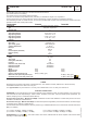
Technical data M 1.5 TS 300 KS - KSX REV.0-04/14 The TS 300 engine driven welder ia a unit which ensures the function as: a) a current source for arc welding b) a current source for the auxiliary power generation It is meant for industrial and professional use, powered by an endothermic engine; it is composed of various main parts such as: engine, alternator, electric and electronic controls, the fairing or a protective structure.
M 1.6 TS 300 KS - KSX Technical data REV.0-04/14 Technical data TS 300 KS TS 300 KSX D.C. WELDING C.C. Welding current regulation (I Scale) Service Regulation of welding * Open circuit voltage Welding voltage 20 - 300 A 300 A - 60%, 250 A - 100% 0-9 70 V 20 - 32 V OUTPUT CARACTERISTIC 0 - 9* Welding current regulator position % 0 25 50 75 100 approx.
M 2 WARNINGS REV.1-02/14 The installation and general warnings regarding operations are aimed achieving correct use of the machine and/or apparatus in the place where it is used as a genset and/or motor welder. - Advice to the User about the safety: + NB: The information contained in the manual can be changed without notice. Any damage caused in connection with the use of these instructions shall not be considered as they are only indicative.
M 2-1 SYMBOLS AND SAFETY PRECAUTIONS REV.2-06/10 STOP - Read absolutely and be duly attentive Read and pay due attention ! GENERAL ADVICE - If the advice is not respected damage can happen to persons or things. HIGH VOLTAGE - Attention High Voltage. There can be parts in voltage, dangerous to touch. The non observance of the advice implies life danger. FIRE - Danger of flame or fire. If the advice is not respected fires can happen. HEAT - Hot surfaces.
PRECAUTION (ENGINE DRIVEN WELDER) M 2-5-1 REV.0-03/00 INSTALLATION AND ADVICE BEFORE USE The operator of the welder is responsible for the security of the people who work with the welder and for those in the vicinity. The security measures must satisfy the rules and regulations for engine driven welders. The information given below is in addition to the local security norms. Estimate possible electromagnetic problems in the work area taking into account the following indications. 1.
M 2.6 INSTALLATION AND ADVICE REV.1-06/07 INSTALLATION AND ADVICE BEFORE USE GASOLINE ENGINES + Use in open space, air swept or vent exhaust gases, which contain the deathly carbone oxyde, far from the work area. Check that the air gets changed completely and the hot air sent out does not come back inside the set so as to cause a dangerous increase of the temperature. 1,5 1,5 m DIESEL ENGINES + Use in open space, air swept or vent exhaust gases far from the work area.
D E NL Luftzirkulation Instalación TS 300 KS-KSX TS 300 EP1 M 2.
D E NL Abmessungen Dimensiones TS 300 KS-KSX M 2.7.
M 3 UNPACKING REV.1-02/04 NOTE ! + Be sure that the lifting devices are: correctly mounted, adequate for the weight of the machine with it’s packaging, and conforms to local rules and regulations. When receiving the goods make sure that the product has not suffered damage during the transport, that there has not been rough handling or taking away of parts contained inside the packing or in the set. In case you find damages, rough handling or absence of parts (envelopes, manuals, etc.
M 4 TRANSPORT AND DISPLACEMENTS COVERED UNITS REV.1-06/10 ! NOTE Transportation must always take place with the engine off, electrical cables and starting battery disconnected and fuel tank empty. Be sure that the lifting devices are: correctly mounted, adequate for the weight of the machine with it’s packaging, and conform to local rules and regulations. Only authorized persons involved in the transport of the machine should be in the area of movement.
TRANSPORT AND DISPLACEMENTS COVERED UNITS M 4-1 REV.2-09/11 ! NOTE Transportation must always take place with the engine off, electrical cables and starting battery disconnected and fuel tank empty. Be sure that the lifting devices are: correctly mounted, adequate for the weight of the machine with it’s packaging, and conform to local rules and regulations. Only authorized persons involved in the transport of the machine should be in the area of movement.
CTM300 CTL300 ASSEMBLY M 6.4 REV.0-09/00 ! ATTENTION The CTL accessory cannot be removed from the machine and used separately (actioned manually or following vehicles) for the transport of loads or anyway for used different from the machine movements. TRAILERS The machines provided for assembling the accessory (slow towing trolley) can be towed up to a maximum speed of 40 Kms/hour on asphalted surfaces.
Set-up for operation (Engine diesel) Air cooled systems M 20 REV.1-09/05 OIL BATH AIR FILTER BATTERY WITHOUT MAINTENANCE Connect the cable + (positive) to the pole + (positive) of the battery (after having taken away the protection), by properly tightening the clamp. Check the state of the battery from the colour of the warning light which is in the upper part. - Green colour: battery OK - Black colour: battery to be recharged - White colour: battery to be replaced DO NOT OPEN THE BATTERY.
M 21 ENGINE STARTING AND USE (DIESEL ENGINES) REV.0-06/99 Check daily ENGINES WITHOUT ACCELERATOR LEVER lnsert the electric protection device (D-Z2-N2) lever towards above and, where mounted, check the isolation monitor (A3) see page M37 – NOTE ! Do not alter the primary conditions of regulation and do not touch the sealed parts. ENGINES WITH MANUAL RECOIL Hold the starting handle firmly. OFF ON START Introduce the key (Q1), turn it clockwise completely, leaving it as soon as the engine starts.
M 21.1 ENGINE STARTING AND USE (DIESEL ENGINES) REV.0-06/99 ENGINE WITH PREHEATING GLOW PLUGS Turn the starter key (Q1) on the position "preheating glow plugs" (the glow plugs light will be on I4), when the light is off, turn the starter key completely clockwise until the engine begins to fire. Let the engine run for some minutes before drawing the lood. ENGINES WITH R.P.M. ELECTRONIC ADJUSTER (ONLY FOR GENERATING SET) Turn the starter key (Q1) completely clockwise until the engine begins to fire.
M 22 STOPPING THE ENGINE (DIESEL ENGINE) REV.0-10/00 Before stopping the engine it is compulsory to effect the following operations: - stop to draw three/single-phase current from the auxiliary sockets. OFF ON START Remove the key (Q1) turning it counter clockwise, OFF position, then take it out. NB.: for safety reason the key must be kept by qualified personel. ENGINES WITH R.P.M. ELECTRONIC ADJUSTER (ONLY FOR GENERATING SET) - stop to draw power from the welding sockets (only for TS models).
4A 9 10 12 15 16 17 19 22 23 24 24A 24B 25 26 27 28 29 30 31 31A 31B 31C 32 33 34 34A 35 36 37 42 42A 47 49 54 55 55A 56 59 59A 59B 59C 59D 59E 59F 63 66 67A 68 69A 70 71 72 73 74 75 76 79 86 86A 87 88 A3 A4 B2 B3 M 30 CONTROLS LEGENDE REV.3-04/13 Hydraulic oil level light Welding socket ( + ) Welding socket ( - ) Earth terminal A.C. socket Accelerator lever Feed pump 48V D.C.
Comandi Controls Commandes D E NL Bedienelemente Mandos TS 300 KS-KSX M 31 M N D L F T D1 E.P.1 LOW ENGINE OK PRESS.
M 34 USE AS WELDER REV.0-10/99 This symbol (Norm EN 60974-1 security standards for arc welders ) signifies that the welder can be used in areas with increased risk of electrical shock. ! ATTENTION The sockets, after the machine is started (see pages M21-26), also with no cables, are anyway under voltage. ! ATTENTION The areas, access of which is forbiden to unqualified personel, are: - the control switchboard (front) - the exhaust of the endothermic engine - the welding process.
M 34.1 USE AS WELDER REV.0-10/99 MACHINE WITH REDUCTION SCALE SWITCH For small electrodes (up to Ø 3.25-130A and 4-200A) it is recommended to use the reduction scale switch (I3) allowing a more XXX A accurate regulation of the welding current max (lever position at 130 A and/or 200A). 100% When using electrodes of a diameter greater than 3.25 and/or 4 set the welding scale knob to 100% and/or max. position. The arc regulator (T) functions equally between both positions (100%-130A and/or 200A).
M 37 USE AS A GENERATOR REV.0-06/99 + It is strictly forbidden to connect the group to the public mains a/o to another source of electric power. + N.B.:if the warning light does not flash, check the accelerator which must bebat its maximum, or the fuse of the relevant socket. (single-phase) or the thermoprotection. ! WARNING Sockets are not self-locked: tension is avaible immediately after starting also with no plug.
M 37.1 USE AS A GENERATOR REV.0-06/99 TS ... PL VERSION Start the machine and wait for the end of the preheating time imposed by the EP1, EP2, EP5 engine protection device. - See pages M39... Press the „generation possibility“ push button (B5) placed on the font side of machine. The voltmeter will show the auxiliary voltage which, for machines at 1500/1800 RPM, must. be approx. ≈230V ± 10% and for machines at 3000/3600 RPM (engine idling) must. be approx. ≈180V ± 10%.
ACCESSORY USE REMOTE CONTROL TC2 / TC2/50 M 38 REV.1-06/05 ON OFF PUSH AND SCREW TIGHT The remote control device for regulating the welding current is connected to the front panel by means of a multipole connector. Position welding current adjusting (T) knob at the necessary current value for the diameter and type of electrode. 09/11/99 M38GB To regulate the current from the TC2 / TC2/50, move the switch (7), located above the multipole connector (8), to "ON" position.
USE AND MAINTENANCE M 39.1 ENGINE PROTECTION EP1 REV..1-10/05 ENGINE PROTECTION (EP1) The electronic device EP.1 (D1) is a microprocessor with logic-circuit board that ensures the protection of the engine in case of low oil pressure or engine high temperature. D1.1(G) Low oil temperature/ Cold engine D1.2(V) Engine test/ OK engine Located on the front of the machine, the EP.1 enters in operation when the engine has been turned on with the ignition key. D1.3(R) Low oil pressure D1.
USE OF THE PROTECTION ENGINE PROTECTION ES - EV M 39.4 REV..1-04/03 ENGINE PROTECTION (ES - EV) The devices ES or EV ensure the protection of the engine in case of low oil pressure or engine high temperature.
TROUBLE SHOOTING M 40.1 TS REV.0-04/04 PROBLEM POSSIBLE CAUSE WHAT TO DO No welding current but 1) Defective diode bridge 1) Check the diodes of the bridge auxiliary output is OK 2) Problem with welding current control 2) Is the remote control switch in the inter(PCB) nal position? 3) Check the diodes and SCR’s of the bridge. 4) Check the transformer which supplies power to the welding control PCB.
M 43 MAINTENANCE REV.1-01/13 ! MOVING PARTS can injure WARNING ●● Have qualified personnel do maintenance and troubleshooting work. ●● Stop the engine before doing any work inside the machine. If for any reason the machine must be operated while working inside, pay attention moving parts, hot parts (exhaust manifold and muffler, etc.) electrical parts which may be unprotected when the machine is open.
I GB F M 45 STORAGE REV.0-06/07 In case the machine should not be used for more than 30 days, make sure that the room in which it is stored presents a suitable shelter from heat sources, weather changes or anything which can cause rust, corrosion or damages to the machine. + Have qualified personnel prepare the machine for storage. GASOLINE ENGINE Start the engine: lt will run until it stops due to the lack of fuel. Drain the oil from the engine sump and fill it with new oil (see page M25).
I GB F + M 46 CUST OFF REV.0-06/07 Have qualified personnel disassemble the machine and dispose of the parts, including the oil, fuel, etc., in a correct manner when it is to be taken out of service. As cust off we intend all operations to be made, at utilizer’s care, at the end of the use of the machine.
M 55 RECOMMENDED ELECTRODES (In accordance with A.W.S Standard) REV.0-10/03 The information here below are to be intended only as indicative since the above norm is much larger. For further details please see the specific norms and/or the manufacturers of the product to be used in the welding process. RUTILE ELECTRODES: E 6013 Easily removable fluid slag, suitable foe welding in all position. Rutile electrodes weld in d.c. with both polarities (electrode holder at + or -) and in a.c..
A B C D E F G H I L M N P Q R S T U V Z X W Y A1 B1 C1 D1 E1 F1 G1 H1 I1 L1 M1 N1 O1 P1 Q1 R1 S1 T1 U1 V1 Z1 W1 X1 Y1 A2 B2 C2 D2 E2 F2 G2 H2 I2 L2 M2 N2 O2 P2 Q2 R2 S2 T2 U2 V2 Z2 W2 X2 Y2 A3 B3 C3 D3 M 60 ELECTRICAL SYSTEM LEGENDE : Alternator : Wire connection unit : Capacitor : G.F.I.
D E Ersatzteile Tabla de recambios TS 300 KS-KSX M 61.
D E Ersatzteile Tabla de recambios TS 300 KS-KSX M 61.
D E Ersatzteile Tabla de recambios TS 300 KS-KSX M 61.
D E Ersatzteile Tabla de recambios TS 300 KS-KSX M 61.
D E Ersatzteile Tabla de recambios TS 300 KS-KSX M 61.
D E Ersatzteile Tabla de recambios TS 300 KS-KSX M 61.
D E Ersatzteile Tabla de recambios TS 300 KS-KSX M 61.
WWW.MOSA.IT MOSA div. della BCS S.p.A. Stabilimento di Viale Europa, 59 20090 Cusago (MI) Italia Tel. + 39 - 0290352.