USE AND MAINTENANCE MANUAL LIGHT & ENERGY Codice Code Codigo Kodezahl 8B9729003 TFII9Y J-4x1000 TFII9Y L-4x250 Edizione Edition Edición Ausgabe 10.
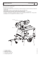
I GB F GENERAL DESCRIPTION M 0 TF II 9 Y J-4x1000 REV.0-10/13 The TF II-9Y J4x1000 a compact and functional model which integrates the functions of lighting tower and electric power generator into a single machine.
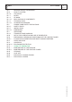
INDEX M0 M 01 M 1.01 M 1.1 M 1.4 M 1.4.1 M 1.5 M 1.5.1 M2 M 2.5 … M 2.7 M 2.7.1 M3 M 4.2 M 20 M 23 M 23.1 M 21 M 31 M 39.12... M 37 -….. M 43 -….. M 43.3 ... M 45 M 46 M 60 M 61-….. TF II 9 Y J-4x1000 M 1 REV.
M 1.1 Notes REV.0-10/13 INFORMATION GENERAL INFORMATION Dear Customer We wish to thank you for having bought a high quality product. ANY USE OF THIS PRODUCT OTHER THAN THOSE EXPLICITELY INDICATED IN THIS MANUAL RELIEVE THE MANUFACTURER FROM ANY RESPONSIBILITY ABOUT DAMAGES THAT MAY OCCUR TO PERSONS, OR PROPERTY. Our sections for Technical Service and Spare Parts will work at best to help you if it were necessary.
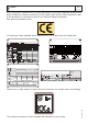
M 1.4 CE MARK REV.7-02/14 Any of our product is labelled with CE marking attesting its conformity to appliable directives and also the fulfillment of safety requirements of the product itself; the list of these directives is part of the declaration of conformity included in any machine standard equipment. Here below the adopted symbol: CE marking is clearly readable and unerasable and it can be either part of the data-plate. TYPE SERIAL N° Made in UE-ITALY TYPE/N° VOLTAGE(V) POWER(W) Hz G P.F. I.
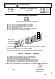
I GB F Dichiarazione conformità Declaration of conformity Déclaration de conformité Konformitätserklärung Declaración de conformidad Declaração de conformidade BCS S.p.A. M 1.4.1 REV.2-10/13 Stabilimento di Cusago, 20090 (Mi) - Italia V.le Europa 59 Tel.
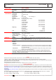
I GB F TECHNICAL DATA Technical data LIGHTS AND MAST GENERAL CHARACTERISTICS TF II 9 Y J-4x1000 REV.0-10/13 Lamp type Mast rotation Mast Wind load stability Tank capacity Running time Ip protection Acoustic power Stabilizers Dimensions (l x w x h) (mm) Weight (dry) Tyres ENGINE GENERATOR CONTROL PANEL M 1.
I GB F ILLUMINATION DIAGRAM Power Titano 1000 W Flux (each lamp) 85000 lm Light type Osram HQI-T 1000W/D Color temperature 7500 °K Mounting height 9m M 1.5.1 REV.
M 2 SYMBOLS AND SAFETY PRECAUTIONS REV.0-10/13 SYMBOLS IN THIS MANUAL - The symbols used in this manual are designed to call your attention to important aspects of the operation of the machine as well as potential hazards and dangers for persons and things. Moreover, this symbolism intends to draw your attention with the aim to give you indications for a correct use and, as a result, to obtain a good operation of the machine or equipment used.
SAFETY RULES GENERAL SAFETY INSTRUCTIONS + NOTE: the information contained in this manual are subject to change without notice. The instructions in this manual are intended as indicative only. It is the responsibility of the owner/operator to evaluate risks and potential damages in relation to the use of the product in the specific conditions of application. Remember that the non observance of the indications of this manual may result in damage to people or things.
SAFETY RULES • Before raising the mast extract the outriggers located at the sides of the machine. Acting on the outriggers level the lighting tower making use of the bubble, so as to bring the equipment in a horizontal position. Make sure that the tower rests securely on the outriggers. If the lighting tower is mounted on road trailer pull the handbrake.
Installazione Installation Installation Luftzirkulation Instalación TF II 9 Y J-4x1000 M 2.7 REV.0-10/13 M1.4 Made in UE-ITALY TYPE SERIAL N° TYPE/N° VOLTAGE(V) POWER(W) Hz P.F. G I.CL. n KVA V(V) I(A) IN ACCORDANCE LTP POWER TEMP. RPM ALTIT. kW WITH ISO °C m 8528 IP Kg M1.
Dimensioni Dimensions Dimensions Abmessungen Dimensiones TF II 9 Y J-4x1000 M 2.7.1 2259 REV.
Abmessungen Dimensiones TF II 9 Y J-4x1000 M 2.7.2 REV.
Dimensioni Dimensions Dimensions Abmessungen Dimensiones TF II 9 Y J-4x1000 M 2.7.3 REV.
M 3 UNPACKING REV.1-02/04 NOTE ! + Be sure that the lifting devices are: correctly mounted, adequate for the weight of the machine with it’s packaging, and conforms to local rules and regulations. When receiving the goods make sure that the product has not suffered damage during the transport, that there has not been rough handling or taking away of parts contained inside the packing or in the set. In case you find damages, rough handling or absence of parts (envelopes, manuals, etc.
I GB F M 4.2 Transport and handling REV.0-10/13 General precaution when handling the machine. ATTENTION OK OK ! During handling of the lighting tower is essential to pay close attention. All handling operations must be performed by qualified personnel. For the characteristics of weight and size, an error during the handling of the machine may result in serious damage to the surrounding people and to the machine itself.
I GB F M 4.2.1 Transport and handling REV.
Set-up for operation Water cooled systems M 20 REV.0-10/13 BATTERY WITHOUT MAINTENANCE Connect the cable + (positive) to the pole + (positive) of the battery (after having taken away the protection), by properly tightening the clamp. Check the state of the battery from the colour of the warning light which is in the upper part. - Green colour: battery OK - Black colour: battery to be recharged - White colour: battery to be replaced DO NOT OPEN THE BATTERY.
I GB F Set-up for operation Water cooled systems M 20.1 REV.0-10/13 COOLING LIQUID ! ATTENTION Do not remove the radiator tap with the motor in operation or still hot, as the liquid coolant may spurt out and cause serious burns. Remove the tap very carefully. Remove the tap and pour the liquid coolant into the radiator; the quantity and composition of the liquid coolant are indicated in the motor operating manual. Replace the tap, ensuring it is perfectly closed.
I GB F Preliminary checks and positioning Start-up M 23 REV.
I GB F M 23.1 Floodlights orientation and mast raising/lowering Start-up REV.0-10/13 ORIENTATION OF FLOODLIGHTS AND MAST RAISING AND LOWERING OF THE MAST ! ATTENTION Before starting the engine, make sure that switches of the lamps on the panel are all in OFF position. 1 3 2 Start the generator with the key on the front panel, following the instructions in the section "START AND STOP (EP6)". Put the circuit breaker (A) in ON position.
I GB F M 21 START AND STOP (EP6) REV.0-10/13 Check daily ! NOTE Do not alter the primary conditions of regulation and do not touch the sealed parts. The starting of the lighting tower can be effected in 2 different modes: 2) Remote starting with TCM35 Put the “Local/Remote” selector on Local. Connect TCM35 to the plug on the front panel and put the switch on “0”.
Comandi Controls Commandes Bedienelemente Mandos TF II 9 Y J-4x1000 REV.0-10/13 5 6 7 8 1 2 4 3 9 10 11 12 POS.
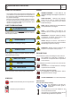
PROTECTIONS M 39.12 EP6 ENGINE PROTECTION REV.1-03/11 4 digits DISPLAY [UP DOWN] Button Ideograms Green LED engine on Button [AUTO] Button [F1] AUTO (Yellow Led) Button [ENTER] (*) Button [+] Key (*) (OFF-ON-START) Button [-] (*) (*) The use of these buttons is reserved only to the manufacturer of the generating set. 1.0 INTRODUCTION The EP6 features Engine and Generating Set control and monitoring.
PROTECTIONS EP6 ENGINE PROTECTION M 39.12.1 REV.1-03/11 [OIL] [ °C ] [O.SPd.] [U.SPd] [bELt] [ALAr] [FUEL](1) [FAIL] [E 04] [E 05](2) [Hi H](2) [Lo H](2) [Hi U] (2) [Lo U](2) [XX.
PROTECTIONS EP6 ENGINE PROTECTION M 39.12.2 REV.0-10/05 Parameter [Default] [P.0] Remote Start Delay Timing (Input #7) [ 1"] Range: 1-59 secs or 1-15 mins Seconds or minutes of continuous REMOTE START command to initiate the automatic engine start (see section 7.0 and [P20] in this section). Remote Stop Delay Timing (Input #7) [ 1"] Range: 1-59 secs or 1-15 mins Seconds or minutes of continuous absence of the REMOTE START command to initiate the stop cycle (see section 7.0 and [P.20] in this section).
PROTECTIONS EP6 ENGINE PROTECTION M 39.12.3 REV.1-03/11 [P.18] [P.19] [P.20] [P.21] [P.22] [P.23] [P.24] [P.25] [P.26] [P.27] [P.28] [P.29] [P.30] [P.31] Alarm Output Timing [ 1'] [inh.] 1-59 secs 1-15 mins and [cont]. Time-out of the alarm output. The code [cont] disables the time-out, and the alarm remains energized until the OFF operating mode is selected. The [inh.] mode enables the use of the external contactor Temperature Switch [n.o.] Selection: [n.o.] or [n.c.] [n.o.
PROTECTIONS EP6 ENGINE PROTECTION M 39.12.4 REV.1-03/11 7.0 REMOTE START The EP6 features REMOTE START only in AUTO operating mode. To operate the REMOTE START, follow the instructions. The EP6 will start the engine after the programmed number of days and the engine will run for the programmed time. To determine how the Automatic Periodic Test is programmed enter the Reading Mode (section 6.0 parameter [P.26] and [P.27]).
M 43 MAINTENANCE REV.1-01/13 ! MOVING PARTS can injure WARNING ●● Have qualified personnel do maintenance and troubleshooting work. ●● Stop the engine before doing any work inside the machine. If for any reason the machine must be operated while working inside, pay attention moving parts, hot parts (exhaust manifold and muffler, etc.) electrical parts which may be unprotected when the machine is open.
I GB F HYDRAULIC POWER PACK MAINTENANCE M 43.3 REV.0-10/13 WIRE ROPES A B Periodically check that the steel ropes of the mast are in perfect conditions. If there is evidence of wear, abrasion, broken wires or loose connection do not use the lighting tower and plan immediately the cables replacement . CAUTION: When replacing use ropes of the same type of the originals. For this purpose, it is highly advisable to use original spare parts. PULLEYS C A. Electric Motor B.
WWW.MOSA.IT MOSA div. della BCS S.p.A. Stabilimento di Viale Europa, 59 20090 Cusago (MI) Italia Tel. + 39 - 0290352.