MoTeC ADL2 / EDL2 User’s Manual Contents Introduction ........................................................................ 1 Overview ............................................................................. 2 ADL2 New Features............................................................................................ 2 Display ................................................................................................................ 4 Alarms...................................................
Checking Operation .......................................................................................... 43 Sensor Zeroing ................................................................................................. 44 Details Editor .................................................................................................... 44 Windows Keyboard Use .................................................. 45 Main Menu ..............................................................................
MoTeC Introduction 1 Introduction Thank you for purchasing a MoTeC ADL2 Dash / Logger and/or EDL2 Enclosed Data Logger ADL2 The MoTeC ADL2 Dash / Logger is a combined LCD dash unit and high performance data logger. EDL2 The EDL2 is a model of the ADL2 that is manufactured without a display screen. Aside from this, it functions in the same way, using the same software as the ADL2.
2 Overview Overview ADL2 New Features The ADL2 replaces the original ADL and includes the following new features. USB Communications This allows the ADL to be connected directly to the PCs USB port rather than requiring the MoTeC CAN Cable which connects to the PCs printer port. The USB cable may be used for all communications to the ADL.
MoTeC Overview 3 Additional CAN Templates The ADL2 provides ten additional CAN templates. Independent Speed Inputs All four speed inputs may be independently designated as hall or magnetic (rather than in pairs). More User Tables The ADL2 has sixteen 2D tables and sixteen 3D tables. Increased Processing Performance The ADL2 has increased processing performance to handle more demanding applications.
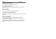
4 Overview Display The ADL2 display is a high contrast, high temperature, custom made LCD display. The display contains a Bar Graph, three Numeric Displays, a Centre Numeric Display and a Bottom Alpha / Numeric Display. Bar Graph The 70 segment bar graph has a user definable range and is typically used as a tacho, however it can be used to display any other value. When used as a tacho it may be configured for up to 19,000 RPM.
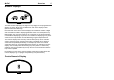
MoTeC Overview 5 Numeric Displays The three numeric displays (Left, Right and Top Right) can be programmed to display any value, which may be different for each of the display modes (Race Practice and Warmup). Note that each of the three numeric displays has a different number of digits and are therefore suited to displaying different values.
6 Overview The Centre Numeric display is incorporated to show the current gear but may be used for other purposes. Bottom Display The 13 digit alpha numeric display can display up to 20 lines of information that can be scrolled up or down using the external buttons. Each of the 20 lines can display up to 3 channel values at a time. The values shown may be different for each of the three display modes. Additionally the bottom display can show up to four override values, similar to the numeric displays.
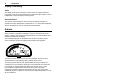
MoTeC Overview The warm up display is used to display important engine sensor readings during engine warm up, eg, RPM, Battery Voltage, Engine Temperature, Oil Pressure, Oil Temperature & Fuel Pressure. The bottom display may be used display many other values that may need checking during warm up. Practice The practice display is used to display basic information, plus information to help the driver improve lap times, eg.
8 Overview Display Formatting Units The display units can be changed to suit the driver, for example the driver may prefer to see the engine temperature in Fahrenheit rather Celsius. This is independent of the units used for other purposes. Decimal Places The number of decimal places can be reduced for display purposes, for example the engine temperature is measured to 0.1 °C but is better displayed with no decimal places. This is normally done automatically.
MoTeC Overview 9 The comparison values can be automatically incremented or (decremented) when an alarm occurs. For example the engine temperature alarm may be set at 95°C with and increment of 5°C, so that the second time the alarm activates it activates at 100°C. A limit may be set on the number of times the comparison value is allowed to increment, also it may return to its original value after a period of time, in case the alarm condition was temporary.
10 Overview Update Rate Not all values are updated 1000 times per second, and logging them faster than their update rate will simply waste memory.
MoTeC Overview 11 Start and Stop Logging Conditions To avoid logging unnecessary data, logging can be started and stopped by user definable conditions. For example logging might start when the vehicle exceeds 50 km/h, and stop when the engine RPM is below 500 RPM for 10 seconds. Note that the Start Condition must be true and the Stop Condition must be false before logging will start.
12 Overview Memory Occupied The amount of memory occupied by Fastest Lap logging depends on how many items are logged, how fast they are logged and the specified maximum Lap Time. The effect on normal logging time is shown in the configuration software. Logging Setup Files The logging list can be saved and loaded from a file. This allows multiple logging setups to be used. Retrieving the Logged Data A personal computer is used to unload the logged data from the ADL2.
MoTeC Overview 13 Other Functions The ADL2 can perform many other functions and calculations including the following: Functions: • Shift Lights • Engine Log (Up to four separate engine logs with separate conditions) Calculations: The ADL2 can calculate and display any of the following: • Lap Time, Lap Speed, Running Lap Time, Split Lap Times, Lap Number, Laps Remaining. • Ground Speed, Drive Speed, Wheel Slip, Lap Distance, Trip Distance, Odometer.
14 Overview Measurement Inputs The ADL2 measurement inputs can be connected to a wide variety of sensors. This allows the ADL2 to measure vehicle parameters such as: Suspension Movement, Wheels Speeds, Steering Angle, Engine Temperature etc. Input Types The ADL2 has a number of different input types which are designed to suit the different types of sensors.
MoTeC Overview 15 Sensors convert a physical measurement (e.g. Pressure) into an electrical signal (e.g. Volts). Different types of sensors generate different types of electrical signals. For example most temperature sensors convert the temperature into a variable resistance signal which may be measured by the ADL2 Temperature inputs, however most wheel speed sensors generate a variable frequency signal which must be connected to either a Digital input or a Speed input.
16 Overview • Absolute Voltage: The sensor voltage is independent of the sensor supply voltage • Ratiometric Voltage: The sensor voltage is proportional to the 5V sensor supply voltage • Variable Resistance: The sensor resistance can be entered directly. • On/Off : The voltage for on and off can be defined Input Voltage Range The measurable input voltage range is 0 to 5.5V on inputs AV1 to 4 and AV11 to 14 and is 0 to 15 Volts on all other AV inputs.
MoTeC Overview 17 Specifications For full specifications see Appendix D: Input Characteristics. Wide Band Lambda Inputs The two high accuracy, fully temperature compensated Wide Band Air Fuel Ratio measurement inputs can be used if the Lambda Option is enabled. These inputs connect directly to a MoTeC 4 wire Wide Band Lambda Sensor and are accurate to 1.5% up to 1.2 Lambda under all load and temperature conditions. Note that this is the Bosch LSM sensor and not the 5 wire Bosch LSU sensor.
18 Overview • Beacon: For connection of a lap beacon Options Note that the number of inputs that are available depends on which options are enabled. See Appendix B: Options Summary for details. Specifications For full specifications see Appendix D: Input Characteristics. Speed Inputs The 4 Speed Inputs are identical to the Digital Inputs except that they can also be configured to suit Variable Reluctance (Magnetic) sensors such as some wheel speed sensors.
MoTeC Overview 19 E888 Analog Inputs Inputs ExA1 to ExA8 are voltage inputs much like the ADL2’s Analog Voltage inputs except that they only accept voltages in the range 0 to 5V and they have a resolution of 4.88mV (10bit). Inputs ExA9 to ExA16 are K type Thermocouple inputs and must use the calibration “E888 K Type Thermocouple”.
20 Overview Note that the number of outputs that are available depends on which options are enabled. See Appendix B: Options Summary for details. For full specifications see Appendix E: Auxiliary Output Characteristics. Expander Outputs Up to two E888 or E816 expanders may be connected to the ADL2. Each expander has 8 outputs are available. The expander outputs can perform all the same functions as the ADL2 outputs.
MoTeC Overview 21 connected devices to communicate with each other, also the CAN port communicates at very at high speed. Other MoTeC products that use CAN for intercommunication include the M800, BR2, PLM and MDD. Note that these devices communicate at 1Mbit/sec, so any other devices connected on the CAN bus must also communicate at 1Mbit/sec. ECU Connection The ADL2 can be connected to most Engine Management Systems (ECUs).
22 Overview Lap Beacon A Lap Beacon can be connected to the ADL2 in order to record Lap Times for display and to provide lap reference information for the data logging analysis software. The MoTeC Lap Beacon consists of a Transmitter which is mounted beside the track and a Receiver which is mounted in the vehicle. Multiple beacon transmitters may also be used to generate split times. For further details refer to the Lap Beacon manual.
MoTeC Overview 23 Interpreter Interpreter is used to analyse the logged data. Data Logging analysis is covered in a separate manual. Telemetry Monitor The Telemetry Monitor software is used to monitor the optional Telemetry link and allows viewing of the telemetry data in various graphical formats such as Charts, Bar Graphs and Dial Gauges. It can also show the vehicles current track position on a track map and compare the current vehicle data to reference data.
MoTeC Installation 25 Installation Mounting Mounting Dimensions Refer to the product dimensions in the Appendices. Attachment Use washers between the unit and the mounting panel to ensure that the unit is mounted only at the mounting points (to avoid twisting the case). The ADL2 has three threaded mounting posts, while the EDL2 has four mounting holes. Do not over tighten the mounting screws (to avoid twisting the case). Vibration isolation may be desirable if the vehicle vibrates severely.
26 Installation Display Care Take care when cleaning the display, use a soft cloth to avoid scratching the display and avoid aggressive solvents. Wiring Pin Connection Details The ADL2 pin connection list appears at the back of this manual. Wire Use 22# Tefzel wire (Mil Spec M22759/16-22) (5 amps max at 100 °C) Note that the Tefzel wire is difficult to strip unless the correct stripping tool is used. Be careful not to nick the wires as this may result in wire failure or poor crimping.
MoTeC Installation 27 Power Wiring Power the ADL2 via a separate switch and a 5 Amp fuse. The separate switch is recommended so that the computer can communicate with the ADL2 without needing to turn the rest of the vehicle power on. Ground Wiring Ground the ADL2 to a good ground. The ground should have a direct connection to the vehicle battery. USB Wiring See Appendix J: USB Wiring for USB wiring details. CAN Bus Wiring Refer to Appendix H: CAN Wiring for details.
28 Installation External Lights All lights including the Shift Lights & Warning Lights must be wired externally. This allows a choice of lights and allows the lights to be placed in the optimum position. Usually LEDs or LED arrays are used. The lights must be wired between one of the Auxiliary Outputs and the ADL2 Battery Positive. The lights must not consume more than 0.5 Amps (6 watts at 12Volts) unless activated via a relay.
MoTeC Installation 29 ADL2 Setup Setup for the ADL2 is done in the ‘Inputs | Communications’ setup screen. Select a communications template that matches the ECU type and ECU telemetry set. In the displayed channel list, check those channels that you wish to receive in the ADL2 Interruption of the Data Note that the data flow to the ADL2 will be interrupted while a computer is connected to the ECU and will not resume for up to 10 seconds after the computer has been unplugged.
30 Installation Telemetry The ADL2 can transmit telemetry information via a radio link. • Note that if RS232 ECU communications is used then the telemetry baud rate must be the same as the ECU communications baud rate (normally 9600 or 19200 baud) Wiring Wiring is dependent on the particular telemetry system, please consult the wiring details supplied with the telemetry system. ADL2 Setup Set the RS232 communications for Telemetry Only, or ECU and Telemetry.
MoTeC Dash Manager Software 31 ADL2 Dash Manager Software Introduction The following is an overview of the main concepts of the ADL2 Dash Manager software. More detailed information is available from the online help provided with ADL2 Dash Manager. Online help is accessed by clicking on the help buttons that appear on most ADL2 Dash Manager screens and by selecting Help from the main menu. Note that the EDL2 uses the same configuration software as the ADL2 and is accessed and operated in the same way.
32 Dash Manager Software The USB port is the recommended connection method because it is much faster however if necessary a MoTeC CAN Cable may be used instead which should be connected to the printer port. Installing ADL2 Dash Manager From a CD-ROM Place the CD-ROM into the CD drive of the pc. A new window will appear. This can be navigated in the same way as a web page. If it does not appear, click on the Windows Start button and select Run. Type ‘D:\Iindex.
MoTeC Dash Manager Software 33 Main Menu The main menu is used to access all of the features of the ADL2 Dash Manager software. Click the mouse on one of the menu items or press the Alt key together with the underlined letter, for example press Alt + F to select the File menu. Unavailable Menu Items When ADL2 Dash Manager is started the items related to changing the configuration will be unavailable, this is because a configuration file has not been selected.
34 Dash Manager Software On line / Off line All changes to the ADL2 configuration are performed ‘Off Line’, i.e. without the PC communicating with the ADL2. Once the configuration changes have been made and saved to a file, they can be sent to the ADL2 which is an ‘On line’ process, i.e. the PC is communicating with the ADL2. Many other functions are also performed ‘On line’, for example, Get Logged Data, Zero Sensors, Monitor Active channels etc.
MoTeC Dash Manager Software 35 Alternatively a new file can be created by loading an existing configuration file and saving it to a new file by selecting File | Save As from the main menu. Opening an Existing File Before an existing configuration file can be modified or sent to the ADL2 it must first be opened. To open a configuration file select File | Open from the main menu and select the desired file.
36 Dash Manager Software Changing the Configuration Once an existing configuration file has been opened, or a new one created the various parts of the configuration may be modified by choosing the appropriate items from the main menu. The configuration setup items are accessed from the main menu items: Inputs, Calculations and Functions. Setup Details For details on each of the ADL2 Dash Manager setup screens click on the Help button that is provided on each screen.
MoTeC Dash Manager Software 37 To check the version of ADL2 Dash Manager select Help | About MoTeC ADL2 Dash Manager from the main menu. To view the ADL2 firmware version, power up the ADL2 – the version is displayed on the bottom line of the display for 2 seconds. Configuration File Version After the ADL2 version has been upgraded the configuration file in the ADL2 must also be updated to match the new version. The display will show a warning until a new configuration has been sent to the ADL2.
38 Dash Manager Software Channels Channels are used to convey information between the various systems of the ADL2. For example an input pin may feed a channel called ‘Engine Temperature’, this channel may then be used by any other system, such as the Display or Data Logging systems.
MoTeC Dash Manager Software 39 Channel List MoTeC has defined an extensive list of channels. All systems within the ADL2 that generate values must choose to feed one of these channels. General Purpose Channels Since the use of all channels can not be predetermined, a number of general purpose channels have been included for occasions when a suitable predefined channel is not available.
40 Dash Manager Software Predefining these properties makes the channels easy to use throughout the rest of the software, for example knowing the measurement type allows the channels to be displayed in any units suitable for that type, with automatic conversion between the units. For example all temperature channels can be displayed in Celsius, Fahrenheit or Kelvin. Channel Names & Abbreviations The channels names may be changed if necessary.
MoTeC Dash Manager Software To expand a category click on the + sign next to the category name.
42 Dash Manager Software Search Method This method lists all channels in alphabetical order and allows a channel to be found either by typing the first few letters of any word in the channel name, or by scrolling through the list. Note that the words may be typed out of order so that ‘Engine Oil Temperature’ could be found by typing "temp eng oil" or "oil t eng" or "e o t” This method is most useful when selecting a channel from the available channels.
MoTeC Dash Manager Software 43 RPM for 2 seconds. Note that this condition could also include a test for when the engine is greater than 500 RPM but set at a lower pressure, which would cover the range from 500 to 1500 RPM, which might read as: Engine Oil Pressure < 50 kPa for 1 second AND Engine RPM > 500 RPM for 5 seconds.
44 Dash Manager Software Tests A number of tests are provided to check the operation of the ADL2, such as the Display Test. To run one of the tests select the appropriate test from the Online menu. Sensor Zeroing Some sensors require regular zeroing, for example Steering Angle, Suspension Position, Ride Heights, G Force Sensors & Throttle Position. ADL2 Dash Manager provides a screen to allow easy zeroing of all these sensors. To zero the sensors select Online | Zero Sensors form the main menu.
MoTeC Windows Keyboard Use 45 Windows Keyboard Use This section gives details on how to use the keyboard with Windows applications. Main Menu The Main Menu can be accessed by holding down the Alt key then pressing the key corresponding to the underlined letter in the menu name, followed by the underlined letter of the item in the drop down menu. Eg Alt F, N for File New. Alternatively press and release the Alt key then select the desired menu item using the arrow keys, then press enter to activate it.
46 Windows Keyboard Use Selecting an Item in a Window To access the various items in a window hold down the Alt key and press the key corresponding to the underlined letter of the item of interest, for example to select the ‘Flash Light’ item press Alt F Alternatively the Tab key may be used to progress from one item to the next (use Shift Tab to move backwards). The selected control is usually indicated by a dotted line around it, or by highlighting the text or item selected within the control.
MoTeC Windows Keyboard Use 47 Hold down the Alt key then press the underlined Letter ( S ), or navigate to the button using the Tab key then press the Enter key or the Space Bar. Check Box A check box is used to tick on or off a particular option. Hold down the Alt key then press the underlined Letter ( F ), or navigate to the Check Box using the Tab key then press the Space Bar. Radio Buttons Radio buttons are used to select an item from a group of options.
48 Windows Keyboard Use A list is used to select from a number of options. Hold down the Alt key then press the underlined Letter of the text above the list ( M ) or navigate to the button using the Tab key then select the desired item using the Arrow keys. Drop down List A drop down list is used to select from a number of items, but only the selected item is shown until a new item needs to be selected.
MoTeC Windows Keyboard Use Tree View A Tree View is used to select items from a hierarchical list Up Arrow = Move the cursor up (selects the item above) Down Arrow = Move the cursor down (selects the item below) Right Arrow = Expand (Expandable branches indicated by a +) Left Arrow = Collapse (Collapsible branches indicated by a -) 49
50 Appendices Appendices Appendix A: General Specifications Physical Case Size ADL2: 180.5 x 91.5 x 18.0 mm (7.1 x 3.6 x 0.7 inches) EDL2: 194.5 x 98.0 x 14.3 mm (excluding connector) Weight 385 grams (0.85 lb) Power Supply Operating Voltage: 7 to 22 Volts DC Operating Current: 0.
MoTeC Appendices Appendix B: Options Summary The following options are available : 50 I/O Option 20 8 4 4 4 8 2 Analog Voltage Inputs Analog Temperature Inputs Switch Inputs Digital Inputs Wheel Speed Inputs Auxiliary Outputs 0 to 1 Volt inputs (10 standard) (4 standard) (4 standard) (2 standard) (4 standard) (4 standard) (2 standard) (using the LA1 & LA2 pins) 16M Memory Option 16 Mbyte of logging memory (8MB standard) Pro Analysis Option Advanced Analysis features in the Interpreter software, incl
52 Appendices Appendix C: Dash Manager Command Line Usage: dash.exe -c[connection] -d -x -l -e -t -s [config file name] [config file name] (Optional) Fully qualified path to the configuration file. (eg "c:\motec\dash\config\bathurst.d30") Note: the path must included the file extension (eg .d30) Options : Each of the following options can be given as "/[character]" or "-[character]". They are shown here as "-[character]".
MoTeC Appendices -e (Optional) Perform a “Get Engine Log” operation. -t (Optional) Perform a “ Get Tell-tale Values” operation. -p (Optional) Perform a “Print Summary” operation. Note: The config file must be specified using a fully qualified path including the file extension. (eg -p "c:\motec\dash\config\bathurst.d30") Note: There must be a space between -p and config name. -s (Optional) Perform a “Send Configuration” operation.
54 Appendices Appendix D: Input Characteristics Analog Voltage Inputs Suitable for : Potentiometers, Voltage output sensors & Variable resistance sensors with a pullup resistor Measurement Voltage Range : Inputs 1 to 4 & 11 to 14: 0 to 5.5 V All other Inputs: 0 to 15.3 V • Note that voltages outside this range may affect the readings on other inputs. Input Resistance : 100k ohms to 0V Resolution : Inputs 1 to 4 & 11 to 14: 1.35 mV All other Inputs: 3.
MoTeC Appendices 55 Measurement Voltage Range : 0 to 15 V • Note that voltages outside this range may affect the readings on other inputs. Input Resistance : 1000 ohms pullup to 5V sensor supply + 100k to 0V Resolution : 3.74 mV Measurement Methods : Ratiometric, Absolute, Variable Resistance, Off/On Update Rate: 500 times / second Filter: 150Hz 1st order Calibration Accuracy Gain (Ratiometric operation) 0.05% max Gain (Absolute operation) 0.
56 Appendices Filter Time Constant: 22usec Digital Inputs Suitable for : Switch to 0V, Logic signal & open collector device (eg Hall Switch) Pullup Resistor : 4700 ohms to 5V Voltage Range : 0 to 15V Positive Trigger Threshold : 3.5 V max Negative Threshold : 1.0 V min Hysteresis : 0.5 V Min Update Rate: 100 times / second Filter Time Constant: 22usec Digital Input Measurement Methods Frequency Resolution 0.
MoTeC Appendices 57 Maximum : 32 msec Pulse Width 100 usec Measures pulse low time Resolution : 100 usec Maximum : 3.2 sec Speed Inputs Can be used in two modes : Hall or Magnetic. In Hall mode a 4700 ohm pullup resistor is connected to 5V and the trigger levels are fixed. In Magnetic mode the pullup resistor is disengaged and the trigger levels can be varied depending on the input frequency.
58 Appendices Pulse Width 1 usec Measures pulse high time Resolution : 1 usec Maximum : 32 msec Pulse Width 100 usec Measures pulse high time Resolution : 100 usec Maximum : 3.2 sec Speed Input Modes HALL Mode Suitable for switch to 0V, Logic signal or open collector device (eg Hall Switch) Pullup Resistor : 4700 ohms to 5V Voltage Range : 0 to 15V Positive Trigger Threshold : 3.0 V max Negative Threshold : 2.8 V min Hysteresis : 0.
MoTeC Appendices Sampling alternates between Group1 and Group2 and is scheduled every 1.
60 Appendices Appendix E: Auxiliary Output Characteristics Output Type : Open Collector (Drives to ground) with weak pullup (10k ohms) to battery positive Current : 0.5 Amp max, current limited & thermal overload protected Output Clamp : 50V Flyback Clamp (No Clamp Diode to supply).
MoTeC Appendices 61 Appendix F: CAN Bus Specification CAN Bus Data Rate: 1Mbit/sec Terminating impedance and data cable impedance: 100 ohms: dictated by the PC communications cable (CAN cable) Maximum length: 16 m including the CAN Cable.
62 Appendices Appendix G: ECU to ADL2 Wiring (RS232) The following details the methods for connecting the various MoTeC ECUs to the ADL2 via RS232. In all cases this is done using the serial data stream generated by the Telemetry function of each ECU. In the case of the M800, M880 and M4e the ADL2 may be directly wired to the ECU because these ECU’s use RS232 interface levels. On the M48, M4 (pre M4e) and the M8 a Computer Interface Module (CIM) or a PCI cable is required to convert the signals to RS232.
MoTeC Appendices 63 M48, M4 (pre M4e) and M8 The M48 & M8 and M4 (pre M4e) require the use of a CIM module or a PCI Cable to convert the logic level signals used by these ECU’s into RS232 levels. Using a CIM Module 79 12 ADL2 M4 / M48 / M8 ECU CIM PC Connector Refer to the CIM module drawing for full wiring details. Note that the data to the ADL2 will be interrupted while a PC is connected.
64 Appendices Using a PCI Cable - Parallel Connection This method allows the PC to be connected without disconnecting the Computer Interface Cable from the ADL2. Adaptor F M PC Interface Cable (PCI Cable) M4 or M8 ECU Adaptor Details 2 3 5 D9 Male M 79 ADL F M 1 to 1 cable D9 Female 2 2 3 5 2 PC F D9 Female Note that the data to the ADL2 will be interrupted while a PC is connected.
MoTeC Appendices 65 Appendix H: CAN Wiring The CAN bus should consist of a twisted pair trunk with 100R (0.25Watt) terminating resistors at each end of the trunk. The preferred cable for the trunk is 100R Data Cable but twisted 22# Tefzel is usually OK. The maximum length of the bus is 16m (50ft) CAN Devices (such as MoTeC ADL2, BR2 etc) may be connected to the trunk with up to 500mm (20in) of twisted wire.
66 Appendices Appendix J: USB Wiring The USB connection should be made by wiring a USB cable to the ADL2 main connector as shown below: The USB cable should have a type B socket so that a standard USB A to B cable can be used to connect between it and the PC. MoTeC can provide a suitable cable (these are not commonly available). Note that the maximum length from ADL to the PC is 5m (16ft) when using a normal USB cable.
MoTeC Appendices 67 Appendix K: Typical Wiring (with BR2) The wiring below shows typical wiring for BR2 on CAN plus USB for PC connection. For more detail on the CAN Bus wiring refer to Appendix H: CAN Wiring. For more details on USB wiring refer to Appendix J: USB Wiring.
68 Appendices Appendix L: Pin List by Function Pin Name Function Battery Power 7 8 BATBAT+ Battery Negative Battery Positive Analog Volt Inputs 45 46 47 48 49 50 19 20 21 22 23 24 25 26 1 2 3 4 5 69 AV1 AV2 AV3 AV4 AV5 AV6 AV7 AV8 AV9 AV10 AV11 AV12 AV13 AV14 AV15 AV16 AV17 AV18 AV19 AV20 Analog Voltage Input 1 Analog Voltage Input 2 Analog Voltage Input 3 Analog Voltage Input 4 Analog Voltage Input 5 Analog Voltage Input 6 Analog Voltage Input 7 Analog Voltage Input 8 Analog Voltage Input 9 Analo
MoTeC 30 31 32 LA1LA2+ LA2- Appendices Lambda Input 1 Negative Lambda Input 2 Positive Lambda Input 2 Negative Switch Inputs 57 58 59 60 SW1 SW2 SW3 SW4 Switch Input 1 Switch Input 2 Switch Input 3 Switch Input 4 Digital Inputs 52 53 54 55 DIG1 DIG2 DIG3 DIG4 Digital Input 1 Digital Input 2 Digital Input 3 Digital Input 4 Speed Inputs 63 64 65 66 SPD1 SPD2 SPD3 SPD4 Speed Input 1 Speed Input 2 Speed Input 3 Speed Input 4 Auxiliary Outputs 9 10 11 12 13 14 15 16 AUX1 AUX2 AUX3 AUX4 AUX5 AUX6 AUX
70 17 27 33 40 43 Appendices 0V 0V 0V 0V 0V Sensor 0V Analog Volt & Analog Temp Sensor 0V Analog Volt & Analog Temp Sensor 0V Analog Volt & Analog Temp Sensor 0V Analog Volt & Analog Temp Sensor 0V Analog Volt & Analog Temp 0V Digital, Switch, Speed 51 56 61 0V 0V 0V Sensor 0V Digital, Switch & Speed Sensor 0V Digital, Switch & Speed Sensor 0V Digital, Switch & Speed CAN Interface 71 72 73 74 75 76 0V 8V CANLA CANHA CANLB CANHB 0V CAN 8V CAN CAN-LO A (Note that 73 is internally connected to 75) CAN-
MoTeC Appendices Appendix M: Pin List by Pin Number Pin Name Function 1 2 3 4 5 6 7 8 9 10 11 12 13 14 15 16 17 18 19 20 21 22 23 24 25 26 27 28 29 30 31 32 33 34 35 36 37 38 39 40 AV15 AV16 AV17 AV18 AV19 Spare BATBAT+ AUX1 AUX2 AUX3 AUX4 AUX5 AUX6 AUX7 AUX8 0V 5V AV7 AV8 AV9 AV10 AV11 AV12 AV13 AV14 0V 5V LA1+ LA1LA2+ LA20V AT1 AT2 AT3 AT4 AT5 AT6 0V Analog Voltage Input 15 Analog Voltage Input 16 Analog Voltage Input 17 Analog Voltage Input 18 Analog Voltage Input 19 Spare Battery Negative Battery
72 41 42 43 44 45 46 47 48 49 50 51 52 53 54 55 56 57 58 59 60 61 62 63 64 65 66 67 68 69 70 71 72 73 74 75 76 77 78 79 Appendices AT7 AT8 0V 5V AV1 AV2 AV3 AV4 AV5 AV6 0V DIG1 DIG2 DIG3 DIG4 0V SW1 SW2 SW3 SW4 0V 8V SPD1 SPD2 SPD3 SPD4 TX/Telem USB-GND AV20 USB-VCC 0V 8V CANLA CANHA CANLB CANHB USB-DM USB-DP RX Analog Temp Input 7 Analog Temp Input 8 Sensor 0V Analog Volt & Analog Temp Sensor 5V Analog Volt & Analog Temp Analog Voltage Input 1 Analog Voltage Input 2 Analog Voltage Input 3 Analog Voltage
MoTeC Appendices Appendix N: Connector ADL2 Mating Connector Deutsch : AS6-20-35SN Wire Wire to suit connector : 22# Tefzel, Mil Spec : M22759/16-22 Crimp Tool Crimp Tool : M22520/2-01 Positioner for Crimp Tool : M22520/2-07 • Note that the Crimp Contacts are type 22D (needed to set the crimp tool correctly) Wire Stripping Tool The following tool is recommended Ideal Industries 45-2133 stripping tool with LB1195 wire stop.
74 Appendices Appendix P: Wire Specifications M22759/16 Wire Ratings (For Various Wire Gauges) Insulation Material : Tefzel Conductor : Tin Plated Copper Voltage Rating : 600 V Maximum Temperature : 150 °C Wire Gauge (AWG) Cross Sectional Area (mm2) Max Current at 100 °C Ambient (Amps) Resistance ( ohm / m ) Resistance ( ohm / 1000 ft ) 22 0.38 5 0.045 14 20 0.61 6 0.028 8.5 18 0.96 9 0.018 5.5 16 1.2 12 0.014 4.3 14 1.9 18 0.009 2.7 12 3.0 24 0.006 1.
MoTeC Appendices Appendix Q: Case Dimensions ADL2 75
76 EDL2 Appendices
MoTeC Notes 77
78 Notes
MoTeC Notes 79
80 Notes