MoTeC AFM1 Air Fuel Ratio Meter
5 June, 2003 Copyright – MoTeC Pty Ltd – 1993-2003 The information in this document is subject to change without notice. While every effort is taken to ensure correctness, no responsibility will be taken for the consequences of any inaccuracies or omissions in this manual.
MoTeC Table of Contents i Specifications..................................................................... 1 Meter .............................................................................................1 Meter Analog Output .....................................................................1 Sensor ...........................................................................................2 Meter Operation.................................................................. 3 Introduction.........
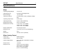
MoTeC Specifications Specifications Meter Operating Voltage Range 7 to 16 V DC Operating Current 0.3 A Max. (Excluding Sensor) Reverse Voltage - 24 V DC Max. Transient Protection 10 Joules (100A / 10ms) (Clamping Voltage 24V) Operating Temperature 0 to 60 deg C Operating Humidity 0 to 80 % Non Condensing Measurement Range 0.75 to 1.60 Lambda Measurement Accuracy ± 1.5% 0.75 to 1.05 Lambda ± 2.5% 1.06 to 1.25 Lambda ± 5.0% 1.26 to 1.60 Lambda Display Update Rate 3.
2 Specifications Sensor Sensor Type Wide Band Heater Voltage 12 to 14 V DC Heater Current 1.5 A Nominal (Hot) 5.0 A Max. (Cold) Operating Temp 250 to 800 C (Heater ON) 450 to 930 C (Heater OFF) * Life Time > 500 Hrs (Unleaded Fuel) > 50 Hrs (Leaded Fuel) Thread Type M18 x 1.5 Note Life Time is dependant on a number of factors - See text.
MoTeC Meter Operation 3 Meter Operation Introduction The MoTeC Air Fuel Ratio Meter measures Lambda (or Air Fuel Ratio) over a wide range of mixtures with fast response time. The display may be set to Show Lambda or Air Fuel Ratio for either Petrol, Alcohol, Gas or Diesel. The Meter provides an Isolated Analog Output Voltage proportional to Lambda that may be connected to MoTeC Engine Management Systems for transmission over the MoTeC Radio Link or closed loop control of Air Fuel Ratio.
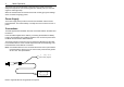
4 Meter Operation The Sensor has an internal heater to heat the sensor quickly and ensure adequate temperature when exhaust gases are relatively cold (i.e. when the engine is under light load). When the internal heater is used the sensor will normally give good readings within 2 minutes of applying power. Power Supply The Power supply must provide current for both the Meter and the Sensor Heater Element. The vehicle battery is usually the most convenient source of power.
MoTeC Meter Operation 5 WARNING Connecting the Meter Sensor Input to anything other than a MoTeC Sensor may render the meter inoperable requiring factory repair. Lambda Lambda gives a measure of Air Fuel Ratio which is independent of the type of fuel being used. Lambda 1.0 corresponds to stoichiometry i.e. when there is no excess fuel and no excess air. Lambda > 1.0 => Excess Air (Lean) Lambda < 1.
6 Meter Operation The display codes are as follows : LA AF P AF A AF g AF d Lambda Petrol Alcohol Gas Diesel Air Fuel Ratio Air Fuel Ratio Air Fuel Ratio Air Fuel Ratio Engine Tuning The desired Air Fuel Ratio (or Lambda) is dependant on the tuning objective i.e. Power, Economy or Emissions. Normally at Full Load the Engine is tuned for maximum power and at light loads the engine is tuned for emissions or economy.
MoTeC Meter Operation 7 Analog Output The Analog Output (3 Pin Connector) provides a voltage proportional to Lambda. The Analog Output may be connected to MoTeC Engine Management Systems for transmission over the MoTeC Radio Link or closed loop control of Air Fuel Ratio. Alternatively the Output may be connected to an Analog Meter or other measurement instrument such as a Data Logger or Chart Recorder. The Output is an Isolated (or Floating) type (i.e. Not Ground Referenced).
8 Meter Operation A. Adjustment During Range Selection The Analog Output may be adjusted while in the Range Select Mode (i.e. While The Display is Showing AO 1 to AO 9). During Range Selection the Analog Output voltage will be set to a predetermined level which is dependant on the selected range. Appendix E shows the voltage level and corresponding Lambda value for the various output modes. The + and - buttons may be used to adjust the output voltage to give the correct reading on the measurement device.
MoTeC Appendices 9 Appendices Appendix A - Lambda to Air Fuel Ratio Table Lambda 0.70 0.75 0.80 0.85 0.90 0.95 1.00 1.05 1.10 1.15 1.20 1.25 1.30 1.35 1.40 1.45 1.50 1.55 1.60 Air Fuel Ratio Petrol 10.3 11.0 11.8 12.5 13.2 14.0 14.7 15.4 16.2 16.9 17.6 18.4 19.1 19.8 20.6 21.3 22.1 22.8 23.5 Alcohol 4.5 4.8 5.1 5.4 5.8 6.1 6.4 6.7 7.0 7.4 7.7 8.0 8.3 8.6 9.0 9.3 9.6 9.9 10.2 LPG 10.9 11.6 12.4 13.2 14.0 14.7 15.5 16.3 17.1 17.8 18.6 19.4 20.2 20.9 21.7 22.5 23.3 24.0 24.8 Diesel 10.2 10.9 11.6 12.
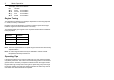
10 Appendices Appendix B - Sensor Wiring Details Female Male Grey Black White White 1 2 2 1 Sensor Sensor+ Battery Battery+ 4 3 2 1 Meter Male Female Battery Negative Battery Positive
MoTeC Appendices 11 Appendix C - Analog Output Wiring Details Positive (Red) Negative (Black) 1 2 3 Meter (3 Pin) Connect the Negative wire to the 0V reference point on the measuring device. Connect the Positive wire to the positive input on the measuring device.
12 Appendices Appendix D - Analog Output Modes Mode Use Lambda 0V 1.6V 5V AO 1 MoTeC 2D/3D-V4 0.50 1.75 AO 2 MoTeC 2D/3D-V3 & M4 0.00 AO 3 General Purpose 0.75 1.00 AO 4 General Purpose 0.75 1.25 AO 5 General Purpose 0.75 1.75 AO 6 General Purpose 0.70 0.95 AO 7 General Purpose 0.70 1.20 AO 8 General Purpose 0.70 1.70 AO 9 Through Connection (Exact Sensor Volts) N/A N/A 1.60 Note The Maximum measurable value of Lambda is 1.
MoTeC Appendices Appendix E - Analog Output Calibration Mode Voltage Lambd a AO 1 4.0V 1.5 AO 2 1.0V 1.0 AO 3 3.0V 0.9 AO 4 2.5V 1.0 AO 5 3.75V 1.5 AO 6 4.0V 0.9 AO 7 3.0V 1.0 AO 8 4.0V 1.5 AO 9 0.
14 Appendices Appendix E - Error Codes Error No Meaning 1 High Sensor Voltage - Possible short to Battery Voltage 2,3,4,5,6,7 Consult MoTeC
Notes
Notes