
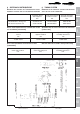
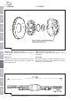
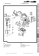
Specifications


8
1
2
3
4
5
6
7
8
9
10
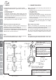
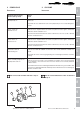
DATI DI CONTROLLO
CHECK DATA
7 BIELLE
15˚
A
A
15˚
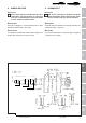
Revisionando le bielle effettuare i seguenti controlli:
- Condizioni delle boccole e gioco tra le stesse e gli
spinotti;
- Parallelismo degli assi;
- Cuscinetti di biella.
I cuscinetti sono del tipo a guscio sottile, con lega
antifrizione che non consente alcun adattamento; se
si riscontrano tracce di ingranamento o consumo oc-
corre senz’altro sostituirli.
- Gioco tra albero motore e cuscinetto di biella a 90° dai
piani di giunzione: min. 0,020, max. 0,061.
CONTROLLO PARALLELISMO DEGLI ASSI
Prima di montare le bielle occorre verificarne la
quadratura. Occorre cioé controllare che i fori testa e
piede di biella siano paralleli e complanari.
L’errore massimo di parallelismo e complanarità dei due
assi della testa e piede biella misurati alla distanza di
200 mm deve essere di ±0,10 mm .
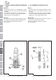
PESO
Il peso della biella completa di viti e boccola superiore,
ma senza semicuscinetti è di 428 ÷ 432 gr.
Fig. 06-09
Coppia di serraggio 30÷32 Nm
Tightening torque 30÷32 Nm
Settore entro il quale deve trovarsi
il taglio della bussola
Sector within which the bushing
opening must lie
Zone di asportazione materiale per
ottenere uguaglianza di peso tra
bielle e corretta ripartizione delle
masse per l’equilibratura.
Material removal area to obtain
identical weight between connecting
rods and correct distribution of
mass for balancing purposes.
N.B. Curare scrupolosamente il parallelismo
degli assi X-X/Y-Y = 0,100 su 200 mm
N.B. Pay the utmost attention to ensuring
perfect parallelism of axes X-X/Y-Y = 0.100 over
200 mm
A
7 CONNECTING RODS
When overhauling the connecting rods perform the
following checks:
- Condition of bushes and clearance between bushes
and gudgeon pins;
- Parallelism of axes;
- Connecting rod bearings.
The bearings are of the thin shell type, with anti-friction
alloy that does not allow any bedding in; if traces of
seizure or wear are noted the bearings must be
renewed immediately.
- Clearance between crankshaft and connecting rod
bearing at 90° from the mating planes: min. 0.020,
max. 0.061.
AXES PARALLELISM CHECK
Before assembling the connecting rods check
squareness. This means checking that the big and small
end bores are perfectly parallel and co-planar.
The maximum parallelism and co-planarity error of the
two axes of the connecting rod big and small ends
measured at a distance of 200 mm must be ±0.10 mm.
WEIGHT
The weight of the connecting rod complete with screws
and upper bushing but without half-shells is 428 ÷ 432.