
User's Manual


APPLICANT: MOTOROLA INC. EQUIPMENT TYPE: ABZ89FC4797-D
EXHIBIT 9
TUNE-UP PROCEDURE
This exhibit contains the tune-up procedure as it will appear in the Configuration Service Software (CSS) manual.
The following adjustments comprise the total transmitter alignment:
1. Reference Oscillator
2. Transmitter Power Output
3. Transmit Deviation Control
4. Reference Modulation Compensation
Note: All adjustments are factory pre-set and do not require alignment under normal operating conditions. In the
event alignment is needed, refer servicing to qualified radio maintenance personnel only.
TEST EQUIPMENT
Description Recommended model
1. Service Monitor Motorola R-2001 or equivalent
2. PC with CSS
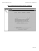
TRANSMITTER ALIGNMENT PROCEDURE
CSS/RSS Port: A 9-pin D connector is provided on the station control module front panel to allow service
personnel to connect a PC loaded with the Configuration Service Software (CSS) and perform programming and
maintenance tasks via this TIA RS-232 port. The following pages of this exhibit will show the important alignment
screens.
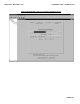
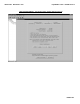
EXHIBIT DESCRIPTION
9A Reference Oscillator Alignment Screen
9B Transmitter Power Output Alignment Screen
9C Transmitter Deviation Alignment Screen
9D Reference Modulation Compensation Alignment Screen
All adjustments are software controlled and are pre-set at the factory. Certain station operating parameters can be
changed via man-machine interface (MMI) commands, within predetermined limits. Examples include transmit /
receiver operating frequencies and power level.