
Instruction Manual

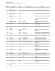

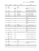


Table Of Contents
- Declaration of Conformity
- Copyrights
- Contact Us
- Document History
- Contents
- List of Figures
- List of Tables
- List of Processes
- List of Procedures
- About GTR 8000 Base Radio
- GTR 8000 Base Radio Description
- 1.1 Introduction
- 1.2 GTR 8000 Base Radio Components
- 1.3 Supported System Configurations
- 1.4 Overview For a GTR 8000 Base Radio in a Trunked IP Simulcast Subsystem
- 1.5 Overview For a GTR 8000 Base Radio in an ASTRO 25 Repeater Site
- 1.6 Overview For a GTR 8000 Base Radio in a Trunked Single-Site Repeater Configuration
- 1.7 Overview For a GTR 8000 Base Radio in a High Performance Data (HPD) Subsystem
- 1.8 Overview for a GTR 8000 Base Radio in Conventional Architectures
- 1.9 Overview of a GTR 8000 Base Radio in a Trunked 3600 System
- 1.10 Power Efficiency Package
- 1.11 License Auditing
- 1.12 GTR 8000 Base Radio Specifications
- 1.12.1 GTR 8000 Base Radio Specifications for Integrated Voice and Data (700/800 MHz)
- 1.12.2 GTR 8000 Base Radio Specifications for Integrated Voice and Data UHF R1 (380–435 MHz)
- 1.12.3 GTR 8000 Base Radio Specifications for Integrated Voice and Data UHF R2 (435–524 MHz)
- 1.12.4 GTR 8000 Base Radio Specifications for Integrated Voice and Data VHF (136–174 MHz)
- 1.12.5 GTR 8000 Base Radio Specifications for High Performance Data (700/800 MHz)
- 1.12.6 Specifications for GTR 8000 Base Radio Cabinet
- GTR 8000 Base Radio Theory of Operation
- 2.1 Functions of the GTR 8000 Base Radio Modules
- 2.2 Backplanes and Card Cages
- 2.3 RFDS Modules
- 2.3.1 RFDS Preselector (700/800 MHz)
- 2.3.2 RFDS Preselector (UHF)
- 2.3.3 RFDS Preselector (VHF)
- 2.3.4 RFDS - Transmit Filter (700/800 MHz)
- 2.3.5 RFDS - Duplexer (700/800 MHz)
- 2.3.6 RFDS - Duplexer (UHF)
- 2.3.7 RFDS - Duplexer (VHF)
- 2.3.8 RFDS - External Dual Circulator/Isolator Tray (700/800 MHz)
- 2.3.9 RFDS - External Dual Circulator/Isolator Tray (UHF)
- 2.3.10 RFDS - External Dual Circulator/Isolator Tray (VHF)
- 2.3.11 Antenna Relay Module
- GTR 8000 Base Radio Installation
- 3.1 Pre-Installation Tasks
- 3.2 General Safety Precautions
- 3.3 General Installation Standards and Guidelines
- 3.3.1 General Site Preparation Overview
- 3.3.2 General Equipment Inspection and Inventory Recommendations
- 3.3.3 General Placement and Spacing Recommendations
- 3.3.4 General Cabinet Bracing Recommendations
- 3.3.5 Mounting Cabinets or Racks to a Floor
- 3.3.6 General Bonding and Grounding Requirements
- 3.3.7 General Cabling Requirements
- 3.3.8 General Power Guidelines and Requirements
- 3.3.9 General Electrostatic Discharge Recommendations
- 3.3.10 FCC Requirements
- 3.3.11 Networking Tools
- 3.3.12 General Installation/Troubleshooting Tools
- 3.3.13 Technical Support for Installation
- 3.4 GTR 8000 Base Radio Hardware Installation
- 3.4.1 Placement and Spacing
- 3.4.2 Cabinet Version of the GTR 8000 Base Radio
- 3.4.3 Rack Mounting The GTR 8000 Base Radio
- 3.4.4 Connecting Power
- 3.4.5 GTR 8000 Base Radio Grounding
- 3.4.6 GTR 8000 Base Radio Rear Connections (Integrated Voice and Data)
- 3.4.7 GTR 8000 Base Radio Rear Connections (HPD)
- 3.4.8 GTR 8000 Base Radio Front Connections
- 3.5 Installation/Troubleshooting Tools
- 3.6 Installing Device Software Prerequisites
- 3.7 Software Download Manager
- 3.8 Installing Devices in the UNC
- GTR 8000 Base Radio Configuration
- 4.1 Configuration Software
- 4.2 Discovering a Device in the UNC
- 4.3 Security/Authentication Services
- 4.4 Device Configuration in CSS
- 4.4.1 CSS Initial Device Configuration
- 4.4.2 Connecting Through a Serial Port Link
- 4.4.3 Serial Connection Configurations
- 4.4.4 Connecting Through an Ethernet Port Link
- 4.4.5 Ethernet Connection Configurations
- 4.4.5.1 Setting the BR/CM Pairing Number in CSS
- 4.4.5.2 Setting the Date and Time in CSS
- 4.4.5.3 Changing SNMPv3 Configuration and User Credentials in CSS
- 4.4.5.4 Customizing the Login Banner in CSS
- 4.4.5.5 Setting the SWDL Transfer Mode in CSS
- 4.4.5.6 Manager IP Address Settings in CSS
- 4.4.5.7 NTP Server Settings in CSS
- 4.4.5.8 Setting the Local Password Configuration in CSS
- 4.4.6 Setting CSS Configuration Parameters for the GTR 8000 Base Radio (Trunked Simulcast)
- 4.4.7 Setting CSS Configuration Parameters for the GTR 8000 Base Radio (Trunked Repeater)
- 4.4.8 Setting CSS Configuration Parameters for the GTR 8000 Base Radio (HPD)
- 4.4.9 Setting CSS Configuration Parameters for the GTR 8000 Base Radio (Conventional)
- 4.4.10 Configuring Tx Power Values and Battery Type
- 4.4.11 Setting RMC System Gain
- 4.5 Configuring Centralized Authentication on Devices in VoyenceControl
- GTR 8000 Base Radio Optimization
- 5.1 Aligning the Internal Frequency Reference Oscillator
- 5.2 Battery Equalization
- 5.3 ASTRO Simulcast Alignment (Trunked Operation)
- 5.4 ASTRO/Analog Simulcast Alignment (Conventional Operation)
- 5.5 Carrier Squelch Alignment
- 5.6 Tx Wireline Alignment
- 5.7 Rx Wireline Alignment
- 5.8 Transmitter Testing
- 5.9 Tuning a Preselector
- 5.10 Tuning a Duplexer
- 5.10.1 Field Tuning Overview
- 5.10.2 Required Test Equipment
- 5.10.3 Tuning a 700/800 MHz Duplexer
- 5.10.4 Tuning a VHF Duplexer
- 5.10.4.1 VHF Duplexer Tuning Setup
- 5.10.4.2 VHF Duplexer Low Pass Resonators Tuning Set Up
- 5.10.4.3 VHF Duplexer High Pass Resonators Tuning Set Up
- 5.10.4.4 VHF Duplexer High Notch Loop Assemblies Tuning Set Up
- 5.10.4.5 VHF Duplexer Low Notch Loop Assemblies Tuning Set Up
- 5.10.4.6 VHF Duplexer Insertion Loss Verification Set Up
- 5.10.4.7 VHF Duplexer Isolation Verification Set Up
- 5.10.4.8 Checking VHF Duplexer After Tuning
- 5.10.5 Tuning a UHF Duplexer
- 5.10.5.1 UHF Duplexer Tuning Set Up
- 5.10.5.2 UHF Duplexer Low Pass Resonators Tuning Set Up
- 5.10.5.3 UHF Duplexer High Pass Resonators Tuning Set Up
- 5.10.5.4 UHF Duplexer High Notch Loop Assemblies Tuning Set Up
- 5.10.5.5 UHF Duplexer Low Notch Loop Assemblies Tuning Set Up
- 5.10.5.6 UHF Duplexer Insertion Loss Verification Set Up
- 5.10.5.7 UHF Duplexer Isolation Verification Set Up
- 5.10.5.8 Checking UHF Duplexer After Tuning
- 5.11 Testing the GTR 8000 Base Radio Performance with a Service Monitor for Integrated Voice and Data
- 5.11.1 Deviation Standards (Digital Operation)
- 5.11.2 Monitoring the Power Supply Module
- 5.11.3 Verifying Receiver Performance for FDMA Operation
- 5.11.4 Verifying Receiver Performance in TTA Operation
- 5.11.5 Verify Receiver Performance for APCO TDMA Operation
- 5.11.6 Verifying Receiver Performance (Analog Operation)
- 5.11.7 Checking Receiver Sensitivity (Self-Test Method) (IV and D)
- 5.11.8 Monitoring the Transmitter Metering Points
- 5.11.9 Verifying Transmitter Performance (Digital Operation)
- 5.11.10 Verifying Transmitter Performance (Analog Operation)
- 5.12 Testing the GTR 8000 Base Radio Performance with a Service Monitor for HPD
- 5.12.1 Setting Up the HPD Service Monitor for Testing the Base Radio
- 5.12.2 Performing In-band Power Meter User Calibration
- 5.12.3 Measuring HPD Base Radio Tx Power, Frequency Accuracy, and Tx EVM
- 5.12.4 Measuring HPD Base Radio Rx Sensitivity and Rx BER
- 5.12.5 Checking Receiver Sensitivity (Self-test Method) (HPD)
- GTR 8000 Base Radio Maintenance
- GTR 8000 Base Radio Operation
- GTR 8000 Base Radio Troubleshooting
- 8.1 GTR 8000 Base Radio General Troubleshooting
- 8.2 GTR 8000 Base Radio Troubleshooting Tools
- 8.3 Site Controller Failure Impact on GTR 8000 Base Radio for Trunked Operation
- 8.4 Conventional Site Controller Failure - Impact on GTR 8000 Base Radio for Conventional Operation
- 8.5 Motorola Solutions Support Center
- GTR 8000 Base Radio FRU Procedures
- 9.1 Field Replaceable Units (FRUs) and Parts
- 9.2 Transceiver Hardware Generations
- 9.3 Power Amplifier Hardware Generations
- 9.4 Replacing a Transceiver Module
- 9.5 Replacing the Fan Assembly
- 9.6 Replacing a Power Supply
- 9.7 Replacing a Power Supply Fan
- 9.8 Replacing a Power Amplifier
- 9.9 Replacing a GTR 8000 Base Radio Backplane
- 9.10 Replacing a Preselector Filter
- 9.11 Replacing Transmit Filters (700/800 MHz)
- 9.12 Replacing the Dual Circulator/Isolator Modules
- 9.13 Replacing a Duplexer (700/800 MHz)
- 9.14 Replacing a Duplexer (UHF)
- 9.15 Replacing a Duplexer (VHF)
- 9.16 Replacing an Antenna Relay
- GTR 8000 Base Radio Reference
- 10.1 GTR 8000 Base Radio LEDs
- 10.2 RFDS Equipment Specifications
- 10.2.1 Transmit Filter Specifications (700/800 MHz)
- 10.2.2 Preselector Filter Specifications (700/800 MHz)
- 10.2.3 Preselector Filter Specifications (UHF)
- 10.2.4 Preselector Filter Specifications (VHF)
- 10.2.5 Duplexer Specifications (700/800 MHz)
- 10.2.6 Duplexer Specifications (UHF)
- 10.2.7 Duplexer Specifications (VHF)
- 10.2.8 External Dual Circulator Specifications (700/800 MHz)
- 10.2.9 External Dual Circulator Specifications (UHF)
- 10.2.10 External Dual Circulator Specifications (VHF)
- 10.2.11 Antenna Relay Specifications
- GTR 8000 Base Radio Disaster Recovery
- Appendix A: Conventional GTR 8000 Base Radio Option Kits
- A.1 T2-2R, T3-3R, and T4-4R Receiver Mute Option Kits
- A.1.1 T2-2R Receiver Mute Option Kit
- A.1.2 T3-3R Receiver Mute Option Kit
- A.1.3 T4-4R Receiver Mute Option Kit
- A.1.4 Expected Site Performance for T2-2R, T3-3R, and T4-4R Receiver Mute
- A.1.5 Tn-nR Receiver Mute Option Kit
- A.1.6 Installing the T2-2R, T3-3R, and T4-4R Receiver Mute Option Kits
- A.1.7 Configuring the T2-2R, T3-3R, and T4-4R Receiver Mute Option Kits
- A.2 T1-2R with Talk-Around Option Kit
- A.3 T2-2R with Duplexer and Triple Relay Option Kit
- A.1 T2-2R, T3-3R, and T4-4R Receiver Mute Option Kits

XCVR Port / Type
Connects to This Device/
Port
Description
trunked circuit-based site, mixed
mode, or digital only.
Reference frequency input,
BNC*
Service monitor Connection port to service moni-
tor for frequency calibration.
* See GTR 8000 Base Radio Time and Frequency Inputs
on page 158.
NOTICE: For information about conventional functions and topologies the
base radio supports,
see the Conventional Operations manual. The base radio can be IP managed while using the 2-
or 4-wire/V.24 interface for channel traffic.
3.4.8.1
System Connector Ports (Conventional)
The system connector, a 50-pin Mini SCSI connector, is used for the WildCard inputs, outputs, and the
analog audio paths not routed to their own connector.
Table 39: 50–Pin System Connector Pin-Outs (Conventional)
Pin No. Signal Type Function Note
1 Aux In 2 Input Main Standby - External
handshaking
Pull To Ground To Activate
2 Aux In 4 Input
Main Standby- Status of oth-
er side
Pull To Ground To Activate
3* Aux In 6 Input In-Cabinet Repeat Pull To Ground To Activate
4 Aux In 8 Input Main Standby - Connectivity
other Station
Pull To Ground To Activate
5 Aux In 9 – Input Phone Patch - PL Strip Opto-Isolated In - Current flow to
Activate
6 Aux In 10 – Input Phone Patch - Monitor Opto-Isolated In - Current flow to
Activate
7 Aux In 11 – Input Opto-Isolated In - Current flow to
Activate
8 Aux In 12 – Input Opto-Isolated In - Current flow to
Activate
9 Aux In 13 Input For future use Pull To Ground To Activate
10 Aux Out 12 Output Low Impedance to Ground When
Active
11 Aux Out 2 Output Phone Patch - Rx Carrier Low Impedance to Ground When
Active
12 Aux Out 4 Output Main Standby - Station Sta-
tus
Low Impedance to Ground When
Active
13 Aux Out 6 Output Low Impedance to Ground When
Active
MN003286A01-H
Chapter
3: GTR 8000 Base Radio Installation
113