
Instruction Manual


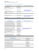


Table Of Contents
- Declaration of Conformity
- Copyrights
- Contact Us
- Document History
- Contents
- List of Figures
- List of Tables
- List of Processes
- List of Procedures
- About GTR 8000 Base Radio
- GTR 8000 Base Radio Description
- 1.1 Introduction
- 1.2 GTR 8000 Base Radio Components
- 1.3 Supported System Configurations
- 1.4 Overview For a GTR 8000 Base Radio in a Trunked IP Simulcast Subsystem
- 1.5 Overview For a GTR 8000 Base Radio in an ASTRO 25 Repeater Site
- 1.6 Overview For a GTR 8000 Base Radio in a Trunked Single-Site Repeater Configuration
- 1.7 Overview For a GTR 8000 Base Radio in a High Performance Data (HPD) Subsystem
- 1.8 Overview for a GTR 8000 Base Radio in Conventional Architectures
- 1.9 Overview of a GTR 8000 Base Radio in a Trunked 3600 System
- 1.10 Power Efficiency Package
- 1.11 License Auditing
- 1.12 GTR 8000 Base Radio Specifications
- 1.12.1 GTR 8000 Base Radio Specifications for Integrated Voice and Data (700/800 MHz)
- 1.12.2 GTR 8000 Base Radio Specifications for Integrated Voice and Data UHF R1 (380–435 MHz)
- 1.12.3 GTR 8000 Base Radio Specifications for Integrated Voice and Data UHF R2 (435–524 MHz)
- 1.12.4 GTR 8000 Base Radio Specifications for Integrated Voice and Data VHF (136–174 MHz)
- 1.12.5 GTR 8000 Base Radio Specifications for High Performance Data (700/800 MHz)
- 1.12.6 Specifications for GTR 8000 Base Radio Cabinet
- GTR 8000 Base Radio Theory of Operation
- 2.1 Functions of the GTR 8000 Base Radio Modules
- 2.2 Backplanes and Card Cages
- 2.3 RFDS Modules
- 2.3.1 RFDS Preselector (700/800 MHz)
- 2.3.2 RFDS Preselector (UHF)
- 2.3.3 RFDS Preselector (VHF)
- 2.3.4 RFDS - Transmit Filter (700/800 MHz)
- 2.3.5 RFDS - Duplexer (700/800 MHz)
- 2.3.6 RFDS - Duplexer (UHF)
- 2.3.7 RFDS - Duplexer (VHF)
- 2.3.8 RFDS - External Dual Circulator/Isolator Tray (700/800 MHz)
- 2.3.9 RFDS - External Dual Circulator/Isolator Tray (UHF)
- 2.3.10 RFDS - External Dual Circulator/Isolator Tray (VHF)
- 2.3.11 Antenna Relay Module
- GTR 8000 Base Radio Installation
- 3.1 Pre-Installation Tasks
- 3.2 General Safety Precautions
- 3.3 General Installation Standards and Guidelines
- 3.3.1 General Site Preparation Overview
- 3.3.2 General Equipment Inspection and Inventory Recommendations
- 3.3.3 General Placement and Spacing Recommendations
- 3.3.4 General Cabinet Bracing Recommendations
- 3.3.5 Mounting Cabinets or Racks to a Floor
- 3.3.6 General Bonding and Grounding Requirements
- 3.3.7 General Cabling Requirements
- 3.3.8 General Power Guidelines and Requirements
- 3.3.9 General Electrostatic Discharge Recommendations
- 3.3.10 FCC Requirements
- 3.3.11 Networking Tools
- 3.3.12 General Installation/Troubleshooting Tools
- 3.3.13 Technical Support for Installation
- 3.4 GTR 8000 Base Radio Hardware Installation
- 3.4.1 Placement and Spacing
- 3.4.2 Cabinet Version of the GTR 8000 Base Radio
- 3.4.3 Rack Mounting The GTR 8000 Base Radio
- 3.4.4 Connecting Power
- 3.4.5 GTR 8000 Base Radio Grounding
- 3.4.6 GTR 8000 Base Radio Rear Connections (Integrated Voice and Data)
- 3.4.7 GTR 8000 Base Radio Rear Connections (HPD)
- 3.4.8 GTR 8000 Base Radio Front Connections
- 3.5 Installation/Troubleshooting Tools
- 3.6 Installing Device Software Prerequisites
- 3.7 Software Download Manager
- 3.8 Installing Devices in the UNC
- GTR 8000 Base Radio Configuration
- 4.1 Configuration Software
- 4.2 Discovering a Device in the UNC
- 4.3 Security/Authentication Services
- 4.4 Device Configuration in CSS
- 4.4.1 CSS Initial Device Configuration
- 4.4.2 Connecting Through a Serial Port Link
- 4.4.3 Serial Connection Configurations
- 4.4.4 Connecting Through an Ethernet Port Link
- 4.4.5 Ethernet Connection Configurations
- 4.4.5.1 Setting the BR/CM Pairing Number in CSS
- 4.4.5.2 Setting the Date and Time in CSS
- 4.4.5.3 Changing SNMPv3 Configuration and User Credentials in CSS
- 4.4.5.4 Customizing the Login Banner in CSS
- 4.4.5.5 Setting the SWDL Transfer Mode in CSS
- 4.4.5.6 Manager IP Address Settings in CSS
- 4.4.5.7 NTP Server Settings in CSS
- 4.4.5.8 Setting the Local Password Configuration in CSS
- 4.4.6 Setting CSS Configuration Parameters for the GTR 8000 Base Radio (Trunked Simulcast)
- 4.4.7 Setting CSS Configuration Parameters for the GTR 8000 Base Radio (Trunked Repeater)
- 4.4.8 Setting CSS Configuration Parameters for the GTR 8000 Base Radio (HPD)
- 4.4.9 Setting CSS Configuration Parameters for the GTR 8000 Base Radio (Conventional)
- 4.4.10 Configuring Tx Power Values and Battery Type
- 4.4.11 Setting RMC System Gain
- 4.5 Configuring Centralized Authentication on Devices in VoyenceControl
- GTR 8000 Base Radio Optimization
- 5.1 Aligning the Internal Frequency Reference Oscillator
- 5.2 Battery Equalization
- 5.3 ASTRO Simulcast Alignment (Trunked Operation)
- 5.4 ASTRO/Analog Simulcast Alignment (Conventional Operation)
- 5.5 Carrier Squelch Alignment
- 5.6 Tx Wireline Alignment
- 5.7 Rx Wireline Alignment
- 5.8 Transmitter Testing
- 5.9 Tuning a Preselector
- 5.10 Tuning a Duplexer
- 5.10.1 Field Tuning Overview
- 5.10.2 Required Test Equipment
- 5.10.3 Tuning a 700/800 MHz Duplexer
- 5.10.4 Tuning a VHF Duplexer
- 5.10.4.1 VHF Duplexer Tuning Setup
- 5.10.4.2 VHF Duplexer Low Pass Resonators Tuning Set Up
- 5.10.4.3 VHF Duplexer High Pass Resonators Tuning Set Up
- 5.10.4.4 VHF Duplexer High Notch Loop Assemblies Tuning Set Up
- 5.10.4.5 VHF Duplexer Low Notch Loop Assemblies Tuning Set Up
- 5.10.4.6 VHF Duplexer Insertion Loss Verification Set Up
- 5.10.4.7 VHF Duplexer Isolation Verification Set Up
- 5.10.4.8 Checking VHF Duplexer After Tuning
- 5.10.5 Tuning a UHF Duplexer
- 5.10.5.1 UHF Duplexer Tuning Set Up
- 5.10.5.2 UHF Duplexer Low Pass Resonators Tuning Set Up
- 5.10.5.3 UHF Duplexer High Pass Resonators Tuning Set Up
- 5.10.5.4 UHF Duplexer High Notch Loop Assemblies Tuning Set Up
- 5.10.5.5 UHF Duplexer Low Notch Loop Assemblies Tuning Set Up
- 5.10.5.6 UHF Duplexer Insertion Loss Verification Set Up
- 5.10.5.7 UHF Duplexer Isolation Verification Set Up
- 5.10.5.8 Checking UHF Duplexer After Tuning
- 5.11 Testing the GTR 8000 Base Radio Performance with a Service Monitor for Integrated Voice and Data
- 5.11.1 Deviation Standards (Digital Operation)
- 5.11.2 Monitoring the Power Supply Module
- 5.11.3 Verifying Receiver Performance for FDMA Operation
- 5.11.4 Verifying Receiver Performance in TTA Operation
- 5.11.5 Verify Receiver Performance for APCO TDMA Operation
- 5.11.6 Verifying Receiver Performance (Analog Operation)
- 5.11.7 Checking Receiver Sensitivity (Self-Test Method) (IV and D)
- 5.11.8 Monitoring the Transmitter Metering Points
- 5.11.9 Verifying Transmitter Performance (Digital Operation)
- 5.11.10 Verifying Transmitter Performance (Analog Operation)
- 5.12 Testing the GTR 8000 Base Radio Performance with a Service Monitor for HPD
- 5.12.1 Setting Up the HPD Service Monitor for Testing the Base Radio
- 5.12.2 Performing In-band Power Meter User Calibration
- 5.12.3 Measuring HPD Base Radio Tx Power, Frequency Accuracy, and Tx EVM
- 5.12.4 Measuring HPD Base Radio Rx Sensitivity and Rx BER
- 5.12.5 Checking Receiver Sensitivity (Self-test Method) (HPD)
- GTR 8000 Base Radio Maintenance
- GTR 8000 Base Radio Operation
- GTR 8000 Base Radio Troubleshooting
- 8.1 GTR 8000 Base Radio General Troubleshooting
- 8.2 GTR 8000 Base Radio Troubleshooting Tools
- 8.3 Site Controller Failure Impact on GTR 8000 Base Radio for Trunked Operation
- 8.4 Conventional Site Controller Failure - Impact on GTR 8000 Base Radio for Conventional Operation
- 8.5 Motorola Solutions Support Center
- GTR 8000 Base Radio FRU Procedures
- 9.1 Field Replaceable Units (FRUs) and Parts
- 9.2 Transceiver Hardware Generations
- 9.3 Power Amplifier Hardware Generations
- 9.4 Replacing a Transceiver Module
- 9.5 Replacing the Fan Assembly
- 9.6 Replacing a Power Supply
- 9.7 Replacing a Power Supply Fan
- 9.8 Replacing a Power Amplifier
- 9.9 Replacing a GTR 8000 Base Radio Backplane
- 9.10 Replacing a Preselector Filter
- 9.11 Replacing Transmit Filters (700/800 MHz)
- 9.12 Replacing the Dual Circulator/Isolator Modules
- 9.13 Replacing a Duplexer (700/800 MHz)
- 9.14 Replacing a Duplexer (UHF)
- 9.15 Replacing a Duplexer (VHF)
- 9.16 Replacing an Antenna Relay
- GTR 8000 Base Radio Reference
- 10.1 GTR 8000 Base Radio LEDs
- 10.2 RFDS Equipment Specifications
- 10.2.1 Transmit Filter Specifications (700/800 MHz)
- 10.2.2 Preselector Filter Specifications (700/800 MHz)
- 10.2.3 Preselector Filter Specifications (UHF)
- 10.2.4 Preselector Filter Specifications (VHF)
- 10.2.5 Duplexer Specifications (700/800 MHz)
- 10.2.6 Duplexer Specifications (UHF)
- 10.2.7 Duplexer Specifications (VHF)
- 10.2.8 External Dual Circulator Specifications (700/800 MHz)
- 10.2.9 External Dual Circulator Specifications (UHF)
- 10.2.10 External Dual Circulator Specifications (VHF)
- 10.2.11 Antenna Relay Specifications
- GTR 8000 Base Radio Disaster Recovery
- Appendix A: Conventional GTR 8000 Base Radio Option Kits
- A.1 T2-2R, T3-3R, and T4-4R Receiver Mute Option Kits
- A.1.1 T2-2R Receiver Mute Option Kit
- A.1.2 T3-3R Receiver Mute Option Kit
- A.1.3 T4-4R Receiver Mute Option Kit
- A.1.4 Expected Site Performance for T2-2R, T3-3R, and T4-4R Receiver Mute
- A.1.5 Tn-nR Receiver Mute Option Kit
- A.1.6 Installing the T2-2R, T3-3R, and T4-4R Receiver Mute Option Kits
- A.1.7 Configuring the T2-2R, T3-3R, and T4-4R Receiver Mute Option Kits
- A.2 T1-2R with Talk-Around Option Kit
- A.3 T2-2R with Duplexer and Triple Relay Option Kit
- A.1 T2-2R, T3-3R, and T4-4R Receiver Mute Option Kits

Chapter 9
GTR 8000 Base Radio FRU
Procedures
GTR 8000 Base Radios are composed of numerous Field Replaceable Units (FRUs) and field
replaceable parts. If you must replace a FRU or part, it is essential to obtain the precise FRU Kit
Number or part number, and to review the replacement procedures provided, including all safety
precautions and system impact information.
This chapter lists the FRUs and Field Replaceable Entities (FREs), and includes replacement
procedures applicable to GTR 8000 Base Radio.
9.1
Field Replaceable Units (FRUs) and Parts
When ordering Field Replaceable Units (FRUs), provide the FRU Kit Number. When ordering field
replaceable parts, provide the part number. Contact Motorola Solutions Support Center (SSC) as
needed for numbers not provided here (for cables internal to a GTR 8000 Base Radio, the part
numbers are not listed in this documentation, but you can locate the part number on the cable before
contacting Motorola Solutions SSC). See Motorola Solutions Support Center
on page 220.
WARNING: To guard against personal injury and/or damage to equipment, place the trunked
base radio in Service Mode when performing service. The GTR 8000 Base Radio periodically
keys up to pseudo train its linear transmitter autonomously when not assigned by the zone
controller. Tx Inhibiting the base radio also prevents the transmitter from keying. Remember to
place the base radio back in Normal Mode when service is complete.
Table 52: GTR 8000 Base Radio Field Replaceable Units
Component Type FRU Kit Number Replacement Procedure
Transceiver Module (700/800
MHz)**
DLN6885A
Replacing a Transceiver Module on
page 232
Transceiver Module (UHF R1, 380–
435 MHz)**
DLN6888A
Transceiver Module (UHF R2, 435–
524 MHz)**
DLN6884A
Transceiver Module (VHF, 136–174
MHz)**
DLN6892A
Transceiver Module w/OCXO Trans-
ceiver Option Card (700/800 MHz)**
DLN6883A
Transceiver Module w/OCXO Trans-
ceiver Option Card (UHF R1, 380–
435 MHz)**
DLN6889A
Transceiver Module w/OCXO Trans-
ceiver Option Card (UHF R2, 435–
524 MHz)**
DLN6886A
MN003286A01-H
GTR 8000 Base Radio FRU Procedures
223