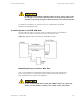
Simulcast Hardware Installation Connecting Power to the STR 3000 Rack Do NOT daisy-chain multiple equipment cabinet grounds using a single ground wire. Doing so increases the overall inductance of the ground wire which can distribute surge energy among the cabinets instead of to the master ground bar. See Standards and Guidelines for Communications Sites (68P81089E50) for detailed information on grounding the rack.
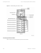
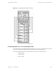
Installing the Expansion Cabinets Chapter 5: Installing the Digital Simulcast Remote Site (10Base-2) For a standard installation, the equipment cabinet is located adjacent to the power supply equipment with a cable loop length less than 10.67 m (35 ft.). The “loop length” refers to the combined length of the -48 VDC lead and the DC return lead. For example, a cabinet which needs 4.87 m (16 ft.) of wire between the power supply equipment and equipment cabinets has a total loop length of 9.75 m (32 ft.).
Simulcast Hardware Installation Figure 5-5 68P81003Y71-O November 2002 Installing the Expansion Cabinets Placement of Expansion Cabinets 5-11
Cabling the STR 3000 Base Radio Rack Chapter 5: Installing the Digital Simulcast Remote Site (10Base-2) Cabling the STR 3000 Base Radio Rack The components of the STR 3000 Base Radio rack are shipped as one unit and do not require separate cabling during the initial installation. For more information on how to cable each component within the rack, see Volume 8, Field Replaceable Units and Entities (68P81004Y55).
Simulcast Hardware Installation Connecting the Transmit Cables The DLN1269A base radio controller module can be configured for both 10Base-2 and 10Base-T operation. The site must be all 10Base-2 or all 10Base-T. You cannot mix configurations within a site. Connecting the Transmit Cables Table 5-5 lists the transmit connections from the STR 3000 rack to the system. For more detail on internal cabling, see Volume 8, Field Replaceable Units and Entities (68P81004Y55).
Connecting the Receive Cables Figure 5-6 Chapter 5: Installing the Digital Simulcast Remote Site (10Base-2) Transmit Cabling in the STR 3000 Rack Connecting the Receive Cables Table 5-6 lists the receive connections from the system into the STR 3000 rack.
Simulcast Hardware Installation Table 5-6 Connecting the Receive Cables Connections for the Receive Cables From STR 3000 Rack Connector Type Port Rx In (Signal IN on figure) 7/16 DIN N Type Destination Device Port Receive antenna Description Connector Type 7/16 DIN N Type Receives antenna input into the STR 3000 rack Figure 5-7 shows the receive cable connections for the STR 3000 rack.
Connecting the V.24 Cabling Chapter 5: Installing the Digital Simulcast Remote Site (10Base-2) Connecting the V.24 Cabling Table 5-7 lists the V.24 audio connections for the STR 3000 rack. Table 5-7 V.24 Cable Connections From STR 3000 Rack Port Connector Type Destination Device Port Description Connector Type Port PNL 1 RJ45 (V.24) Channel Bank 1, SRU Port 1 RJ45 (V.24) Connection to the prime site. Port PNL 2 RJ45 (V.24) Channel Bank 1, SRU Port 2 RJ45 (V.
Simulcast Hardware Installation Figure 5-8 Connecting Cables for a Co-Located Remote Site V.24 Cabling in the STR 3000 Rack Connecting Cables for a Co-Located Remote Site A co-located remote site is installed along with the prime site or very near to it. This allows the co-located remote site to connect directly into the prime site and use the same network structures.
Powering Up the STR 3000 Base Radio Table 5-8 Chapter 5: Installing the Digital Simulcast Remote Site (10Base-2) Cabling Connections from the STR 3000 Rack at a Co-Located Remote Site From STR 3000 Rack Connection Type Port Destination Device Port Description Connectoin Type Ethernet In port on junction panel in the first cabinet BNC Port 1 on Hub BNC Ethernet LAN connection Ethernet In port on the junction panel of succeeding cabinets BNC Ethernet out on panel BNC Ethernet LAN connection
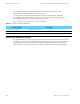
Simulcast Hardware Installation Table 5-9 Status Priorities for Multifunction LEDs LED Status Indicators on the Base Radio LED Name Color Solid Blinks Twice per Second Blinks Once per Second Solid Then Blinks off 1/4 Second Station Operational (ON) Green All N/A N/A N/A Station Failure (Fail) Red FRU failure • Ext Ref Failure • Rx Tx Unlock Config N/A Service/Tx Inhibit (SVC) Yellow N/A Service SVC Tx Inh N/A Control (CTL) Green Control Ch Failsoft N/A ISP Rx Rx Active (Rx)
Operating Specifications for the Base Radio Chapter 5: Installing the Digital Simulcast Remote Site (10Base-2) Table 5-11 lists the operating specifications for an STR 3000 rack. Table 5-11 General Operating Specifications for the STR 3000 Rack Value or Range Specification Number of Channels 1-6 Number of Cabinets 1 Cabinet Height 211 cm (83 in.) (48 RU) Footprint (W x D) 60 x 60 cm (24 x 24 in.
Simulcast Hardware Installation Table 5-12 Operating Specifications for the Transmitter Operating Specifications for the Base Radio Value or Range Specification Dimensions Height: 22.2 cm (8.75 in.) (5 RU) Width: 48.3 cm (19 in.) Depth: 41.9 cm (16.5 in.
Simulcast Hardware Installation Table 5-18 Installing the TRAK 9100 Simulcast Site Reference Operating Specifications for the Tower Top Amplifier Installing the TRAK 9100 Simulcast Site Reference The TRAK 9100 provides a composite 5 Mpps and 1 pps signal used for timing at a remote site. This section describes how the TRAK 9100 simulcast site reference is installed at a remote site.
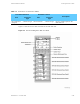
Hardware Modules in the TRAK 9100 Simulcast Site Reference Figure 5-9 Chapter 5: Installing the Digital Simulcast Remote Site (10Base-2) Front View of the TRAK 9100 Simulcast Site Reference Hardware Modules in the TRAK 9100 Simulcast Site Reference Table 5-19 lists the modules that comprise the TRAK 9100 simulcast site reference. Table 5-19 TRAK 9100 Simulcast Site Reference Modules Module Description Antenna See "Installing the GPS Antenna" on page 5-27.
Simulcast Hardware Installation Grounding the Chassis Grounding the Chassis Connect the grounding cable to the ground lug. The ground lug is a screw on the back of the power supply located to the left of the AC power receptacles. Use 6 AWG wire and the appropriate lug connected to chassis ground through to the RGB. Wiring for Power The two AC outlets on the rear of the panel provide power to all of the modules in the TRAK 9100.
GPS Antenna Line Loss Chapter 5: Installing the Digital Simulcast Remote Site (10Base-2) The simulcast system will not operate properly if the GPS receiver is not locked onto at least four GPS satellites. The four satellites are used to establish a three-dimensional fix (latitude, longitude, and altitude) for the site. The TRAK 9100 will free-run for a time period defined by configuration settings.
Simulcast Hardware Installation ALARM INDICATION (NO LOCK ON GPS SIGNAL) ALARM INDICATION (NO LOCK ON GPS SIGNAL) A system alarm indicates when the GPS signal cannot be located and that the antenna may need to be repositioned. Cabling the TRAK 9100 Simulcast Site Reference All output signal connections interfacing to the network are made via the rear panel.
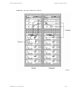
Powering Up the TRAK 9100 Simulcast Site Reference Table 5-21 Chapter 5: Installing the Digital Simulcast Remote Site (10Base-2) Cabling from the Front Connections on the TRAK 9100 Simulcast Site Reference From TRAK 9100 Connector Type Port Destination Device Port Description Connector Type AC Input A IEC 320 Power Outlet Power AC Power AC Input B IEC 320 Power Outlet Power AC Power Ethernet IN RJ45 Port 6 on the Remote Site LAN switch RJ45 Path for the NTP data Ethernet IN RS-232
Simulcast Hardware Installation Figure 5-10 Operating and Environmental Specifications Power Supply Module with LED Indicators Operating and Environmental Specifications Table 5-23 lists the operating and environmental specifications for the TRAK 9100 simulcast site reference. Table 5-23 TRAK 9100 Operating and Environmental Specifications Specification Value or Range Physical Dimensions Height: 13.34 cm (5.25 in.) (3U) Width: 48.26 cm (19 in.) Depth: 38.1 cm (15 in.) Weight Approximately 11.
Overview of the TRAK 9200 Simulcast Site Reference Chapter 5: Installing the Digital Simulcast Remote Site (10Base-2) Overview of the TRAK 9200 Simulcast Site Reference The TRAK 9200 simulcast site reference differs from the TRAK 9100 simulcast site reference with respect to two modules: the power supply and the termination/fault logic unit. The power supply has only one output (5 VDC). So the indicators differ from those referenced in "Powering Up the TRAK 9100 Simulcast Site Reference" on page 5-30.
Simulcast Hardware Installation Operating Specifications Operating Specifications Table 5-30 lists the operating and environmental specifications for the remote site hub. Table 5-30 Remote Site Hub Operating and Environmental Specifications Value or Range Specification Physical Dimensions Height: 4.32 cm (1.7 in.) (1 RU) Width: 44.1 cm (17.4 in.) Depth: 17.0 cm (6.7 in.) Weight 2.1 kg (4.
Installing the Simulcast Remote Site Router Figure 5-21 Chapter 5: Installing the Digital Simulcast Remote Site (10Base-2) Rear View of the Simulcast Remote Site Router Installing the Simulcast Remote Site Router This section describes how to install the simulcast remote site router. Grounding the Chassis Some network topologies require a grounding stud, which is separate from the AC ground on the chassis of the networking equipment.
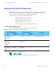
Simulcast Hardware Installation Table 5-31 Powering Up the Simulcast Remote Site Router Cable Connections from the Simulcast Remote Site Router From Remote Site Router Connector Type Port Destination Device Port Description Connector Type LAN 1 RJ45 Remote Site Hub RJ45 Ethernet connection only for co-located LAN 2 RJ45 Remote Site Switch RJ45 Ethernet connection between the hub and the prime site switch Serial 3 60-pin FlexWAN Channel Bank 60-pin FlexWAN Ethernet connection between t
Operating Specifications Chapter 5: Installing the Digital Simulcast Remote Site (10Base-2) Table 5-32 LED Status at Successful Startup LED Status LAN Link On Active On or blinking Fault Off FlexWAN SERIAL Link On Active On Fault Off SYSTEM Status All off Fwd Off or blinking Power/Fault Green Run On Load Off Test Off Operating Specifications Table 5-33 lists the operating specifications for the simulcast remote site router.