APPLICANT: MOTOROLA INC. EQUIPMENT TYPE: ABZ89FC5805 TUNE-UP PROCEDURE There is no field tune-up procedure. All adjustments are software controlled and are pre-set at the factory. Certain station operating parameters can be changed via Man Machine Interface (MMI) through the BRC RS232 port within predetermined limits. Examples include transmit / receiver operating frequencies and power level.
APPLICANT: MOTOROLA INC. EQUIPMENT TYPE: ABZ89FC5805 Tune Up Procedure This exhibit contains the tune-up procedure as it will appear in the Astro® 25 system release 6.2 Simulcast Configuration Manual. The following adjustments comprise the transmitter setups. 1. Reference oscillator installation 2. Setting transmitter frequency and power level. 3. Measuring channel interference 4. Measuring the transmitter metering points 5.
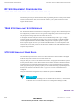
RF SITE EQUIPMENT CONFIGURATION CHAPTER 3: SIMULCAST REMOTE SITE CONFIGURATION RF SITE EQUIPMENT CONFIGURATION ................................... .. The following sections provide information about programming the devices that provide the RF interface (simulcast base radio) to the subscriber radios in your system and the devices that support the RF interface.
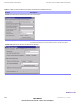
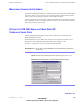
RF SITE EQUIPMENT CONFIGURATION CHAPTER 3: SIMULCAST REMOTE SITE CONFIGURATION TABLE 3-1 SIMULCAST BASE RADIO CONFIGURATION SCREENS IN CSS (CONTINUED) Screen Description FIGURE 3-7 BASE RADIO HARDWARE CONFIGURATION SCREEN Station Configuration Screen Provides for the simulcast base radio’s specific station configuration. See the online documentation provided with the CSS for specific procedures.
SIMULCAST CONFIGURATION ILLEGAL CARRIER DETERMINATION AND BASE RADIO MEASUREMENT MEASURING CHANNEL INTERFERENCE The STR 3000 Simulcast Base Radios log interfering carrier levels that surpass the RF threshold value to the station error log. These logs can be used to determine periodic interfering carriers that are not present long enough to trigger the Carrier Malfunction Timer. These logs should also be checked after any changes are made to the site that affect the site noise floor.
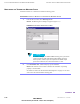
ILLEGAL CARRIER DETERMINATION AND BASE RADIO MEASUREMENT CHAPTER 3: SIMULCAST REMOTE SITE CONFIGURATION MONITORING THE TRANSMITTER METERING POINTS Perform Procedure 3-4 to monitor the transmitter metering points. PROCEDURE 3-4 HOW TO MONITOR THE TRANSMITTER METERING POINTS 1 From the Service menu, select Metering Screen. Results: The Metering Screen dialog box appears (Figure 3-17).
SIMULCAST CONFIGURATION ILLEGAL CARRIER DETERMINATION AND BASE RADIO MEASUREMENT SOURCE OF THE TRANSMITTER METERING POINTS Table 3-4 lists each of the transmitter metering points and where the measurement is taken.
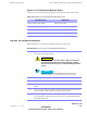
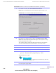
ILLEGAL CARRIER DETERMINATION AND BASE RADIO MEASUREMENT CHAPTER 3: SIMULCAST REMOTE SITE CONFIGURATION PROCEDURE 3-5 HOW TO CHECK THE TRANSMITTER FREQUENCY (CONTINUED) 7 From the Service menu, select Test and Measurement Screen. Result: The Test and Measurement Screen dialog box appears (Figure 3-18). FIGURE 3-18 TEST AND MEASUREMENT SCREEN DIALOG BOX 8 If the station is not already in Service Mode, click Change to Service Mode.
SIMULCAST CONFIGURATION ILLEGAL CARRIER DETERMINATION AND BASE RADIO MEASUREMENT PROCEDURE 3-5 HOW TO CHECK THE TRANSMITTER FREQUENCY (CONTINUED) 14 Disconnect the service monitor from the base radio and reconnect the transmit antenna to the transmit input connector. 15 Turn on the base radio being checked using the On and Off switch on the front of the power supply module and allow the station to fully initialize.