MOSCAD-M™ Remote Terminal Unit Owner’s Manual 68P02961C50-O
CONTENTS INTRODUCTION......................................................................................................................... 1 SCOPE OF THIS MANUAL ............................................................................................................... 1 GENERAL DESCRIPTION ................................................................................................................ 1 HARDWARE OPTIONS ................................................................................
Contents LED Control.........................................................................................................................................13 System Software Downloading ............................................................................................................13 CPU Reset............................................................................................................................................13 LED DISPLAY INDICATIONS ...................................
Contents APPENDIX B: MODELS AND ACCESSORIES .................................................................... 39 GENERAL .................................................................................................................................... 39 INSTALLATION OF MOSCAD-M WITH GP140/328/HT750/ PRO5150 RADIO ........................... 41 MOSCAD-M INSTALLATION KIT FOR GP140/GP328/HT750/ PRO5150 RADIOS .................... 42 MOSCAD-M DEBUG HARDWARE KIT ...........................................
INTRODUCTION Scope of this Manual This manual provides instructions for the installation and operation of the MOSCAD-M ™ Remote Terminal Unit (RTU). It also provides on-site tuning instructions for RTU elements that do not necessarily require shop level assistance. This manual covers the basic RTU and most communications and I/O options. The online help of the MOSCAD-M RTU Configurator contains additional information on the RTU.
Introduction Hardware Options Line, RS232 and RS485 Communication Interfaces A variety of Line, RS232, and RS485 communication interfaces are available: • RS485 adapter • RS232 multiplexer • Ethernet Interface Unit Radio Communication Interfaces A variety of radios can be attached using internal DPSK or duo-binary modem: • Internal radio UHF High Band • Internal radio UHF Low Band • Variety of external radios (GP140/328, HT750, PRO5150) For details on the available external radio models, and th
INSTALLATION General MOSCAD-M SAFETY SUMMARY The MOSCAD-M should be installed by qualified and authorized technicians. If the installation involves high-voltage connections, technicians must be specifically qualified to handle high voltage. This equipment was tested with cables 3 meters in length. If longer cables and/or cabinets are used, the installer is responsible for making sure that the installation complies with the requirements of the relevant standard. The product is a radio accessory.
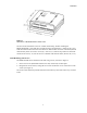
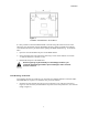
Installation Figure 2 Dimensions of MOSCAD-M RTU Plastic Case The unit can be installed on screws or on DIN rail mounting. Before installing the MOSCAD-M RTU, verify that there is sufficient space around the unit. Allow 20 cm (7.87") from the bottom of the box for the TB connectors. When an RF connector is attached (internal radio models), allow for an extra 10 cm (4"): 2.02 cm (.8") from the top of the box for the RF connector and 8 cm (3.15") for the wires.
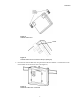
Installation Figure 3 Installation of MOSCAD-M – Screw Mount It is also possible to attach the MOSCAD-M to the wall using the small screw hole at the bottom of case, though this requires dismantling the RTU, which is generally discouraged. Consult Motorola service personnel before opening the MOSCAD-M casing. To mount the RTU: 1. Open the case and dismantle the parts of the MOSCAD-M. 2. Secure the back of the case against the wall using a screw whose diameter is less than 3.
Installation Figure 4 DIN Rail Attachment SNAP Figure 5 DIN Rail Attachment-Foot Element Snap-in (Enlarged) 2. Press the unit onto the DIN rail, using both universal foot elements. The elements can be used on DIN rail 35 mm and G rails. (See Figure 6).
Installation Connections Verify that all power and ground connections are made in accordance with local standards. Ground Connection Connect the grounding cable directly to the protective grounding pins 9 and 10 (PGND) in the main power-in connector (see TB1 in Figure 9). Power Connections The unit can be connected directly to a 9-30V DC source through the main Power-In connector (see Figure 9) where Pin #1 is + (positive) and Pin #2 is – (negative).
Installation If the external radio is connected to an outside power supply, first power on the unit, and then power on the radio. The auxiliary power supply (maximum 2A) can be changed to 6V, 6.5V, 7.5V, 8V, 9V or 9.6V DC by changing the setting of the P11 jumper located on the Main board. (See markings on the board.) To set the power to 8V, remove the jumper and save for future use. This is usually set in the factory according to the external power supply of the radio. The default setting is 9V DC.
Installation Installation of Backup Batteries The backup battery should not be installed before the unit is connected to the main power supply. This may cause the battery to drain. 1. Place 3 “C” size alkaline batteries into the carton cylinder, each in the same direction, as shown in Figure 7 below. Figure 7 Backup Battery Cylinder and 3 Backup C Batteries 2. Place the cylinder with the batteries into the battery case in the direction indicated on the unit (see Figure 8 below).
Installation Miscellaneous Open the Case Door To open the case door properly, press the two clips (latches) and pull the wing to an open position. The cable cover is opened counter-clockwise to expose the cable connections and the backup battery cover is opened clockwise to expose the battery housing. Close the Case Door To close the case door properly, press until the latch clicks. Note that if the batteries in the housing are not inserted properly, the backup battery cover door may not close.
THE MOSCAD-M UNIT Overview The MOSCAD-M RTU (shown below) contains power connections, line communication ports, internal/external radio interfaces, radio modems and I/Os.
The MOSCAD-M Unit Communication Ports The MOSCAD-M RTU has 3 ports available: PORT 1 - RS232 Configurator Port (for programming and monitoring the unit), RS232 External Dialup Modem, or RS485 Communication, User protocol (1A is used for RS485) (1B is used for RS232) PORT 2 – Secondary Port RS232 (User protocol) PORT 3 – External Radio interface Ports 2 and 3 can work simultaneously with each other and with either Port 1A or Port 1B. Ports 1A and 1B cannot work simultaneously.
The MOSCAD-M Unit LED Control Display On/Advance When the display is off, pressing the push-button once, momentarily, activates the display. Every consecutive momentary depression of the push-button advances the display to the next page, in the following order: CPU > IO1 (I/O Page 1-DI) > IO2 (I/O Page 2-DO) > IO3 (I/O Page 3-AI) > Page 4 (AO) > Page 5 (User Application Controlled) > Page 6 (Hardware Test Controlled). The next depression of the push-button returns the display to the CPU.
The MOSCAD-M Unit LED Display Indications A 5 × 4 matrix of LEDs is used for diagnostics and testing of the unit (see Figure 10). The top row indicates to which page or toggle (CPU, IO1, IO2, IO3, Page 4, Page 5, Page 6) the LED panel is set. To advance from one page to another, press the push-button once quickly. The first depression of the push-button activates the display.
The MOSCAD-M Unit Name On/Off Function/Indication LED 13 MON On Controlled by application for user use. LED 2 RST On The CPU is in Reset mode. LED 3 ERR On An error has occurred. LED 4 BATT On The backup battery does not exist or has reached a critical level of 3.5V. LED 6 TX1 On The RTU is transmitting data via Port 1. LED 7 RX1 On The RTU is receiving data via Port 1. LED 8 CM1 On The communication channel used by Port 1 is busy.
The MOSCAD-M Unit IO1 Page LED Functions The following table describes the functions of the diagnostic LEDs when set to the IO1 (Page 1) toggle or display (IO1 LED on). Name On/Off CPU Off Function/Indication Flashing: FPGA is not loaded correctly. IO1 On Display is in IO1 page. IO2 Off IO3 Off LED 1 On DI1 is on. LED 2 On DI2 is on. LED 3 On DI3 is on. LED 4 On DI4 is on. LED 5 On DI5 is on. LED 6 On DI6 is on. LED 7 On DI7 is on. LED 8 On DI8 is on.
The MOSCAD-M Unit IO2 Page LED Functions The following table describes the functions of the diagnostic LEDs when set to the IO2 (Page 2) toggle or display (IO2 LED on). Name On/Off CPU Off Flashing: Function/Indication FPGA is not loaded correctly. IO1 Off IO2 On IO3 Off LED 1 On DO1 is set. LED 2 On DO2 is set. LED 3 On DO3 is set. LED 4 On DO4 is set. LED 5 On DO5 is set. LED 6 On DO6 is set. LED 7 On DO7 is set. LED 8 On DO8 is set.
The MOSCAD-M Unit IO3 Page LED Functions The following table describes the functions of the diagnostic LEDs when set to the IO3 (Page 3) toggle or display (IO3 LED on). Each AI has two LEDS which represent its status (underflow or overflow). When both LEDS are lit, that means that this specific AI is not calibrated. Name On/Off CPU Off Flashing: Function/Indication FPGA is not loaded correctly. IO1 Off IO2 Off IO3 On Display is in IO3 page. LED 1 On AI1 Overflow. LED 2 On AI1 Underflow.
The MOSCAD-M Unit AO Page LED Functions The following table describes the functions of the diagnostic LEDs when set to the AO (Page 4) toggle or display (CPU and IO1 LEDs on). Name On/Off Function/Indication CPU On IO1 On IO2 Off IO3 Off Display is in AO page. LED 1 On AO1 Voltage. LED 2 On AO1 Current. LED 3 On AO1 is uncalibrated.
The MOSCAD-M Unit User Page LED Functions The following table describes the functions of the diagnostic LEDs when set to the User (Page 5) toggle or display (CPU and IO2 LEDs on). The LEDs are controlled by the user ‘C’ Application.
The MOSCAD-M Unit Hardware Test Page LED Functions The following table describes the functions of the diagnostic LEDs when set to the Hardware Test (Page 6) toggle or display (CPU and IO3 LEDs on). The LEDs are controlled by the Hardware Test utility of the MOSCAD-M Configurator.
The MOSCAD-M Unit I/Os (All Models) Wetting switch connection (x2) Two solid state (SS1, SS2) Digital Outputs are provided for wetting/supply voltage control of the DI, AI, or external devices. They are connected to the Power In TB1 (pins 3-8) and can drive up to 400mA each. The switches are equipped with over-current protection, limiting the current driven through each of them to 400 mA maximum. Figure 11 shows how the solid state DOs are to be connected.
The MOSCAD-M Unit DO Magnetic Relay connection (x4) Four magnetically latched Digital Outputs are connected to TB2. They can drive up to 2A. Figure 12 shows how the DOs are to be connected. Figure 12 Main Board Magnetically Latched Digital Output I/O Connection DO Open Collector (x4) Four open collector Digital Outputs are connected to TB2/TB3. The DOs can sink a current of up to 500mA. They are divided into two groups of two, each with a common ground.
The MOSCAD-M Unit DI (x12) Twelve wet Digital Inputs are connected to TB3-TB5. Three of these (DI1-DI3) may be used as Wakeup events for the RTU. DI11-DI12 can be used to count pulses of up to 10KHz. They count the rising edge of the pulse. They can also show the actual state of the DI (On/Off). Figure 14 shows how the DIs are to be connected.
The MOSCAD-M Unit Additional I/Os (Expanded I/O Models only) AI (x4) Four Analog Inputs are connected via TB6. (See Figure 9.) The AIs are 4-20mA or 0-5V. Each AI has a jumper which determines the measurement. If the jumper is placed (closed), the AI is set up to measure current (4-20mA). If it is not placed (removed), it measures voltage (0-5V). The jumpers are placed in the factory based on customer order.
The MOSCAD-M Unit AO (x1) One Analog Output is connected to TB5. The AO is 0-20mA or 0-5V. The AO type (current or voltage) is determined by connecting to the proper pin on the TB and by selecting the proper AO type in the software (either via the Configurator Hardware Test utility or the user software application.) The AO can be driven from an internal or external power supply. The minimum output resistance for voltage is 5KΩ.
The MOSCAD-M Unit DI (x3) An additional 3 wet Digital Inputs are connected via TB5. Figure 17 shows how the DIs are to be connected.
The MOSCAD-M Unit Pin Assignment - Main Board TBs The following charts indicate the function of each pin in the various terminal blocks (TBs) on the Main board as shown in Figure 9.
The MOSCAD-M Unit Pin Assignment - Expansion Board TBs The following charts indicate the function of each pin in the various terminal blocks (TBs) on the Expansion board as shown in Figure 9. TB5 (DI/AO) Pin # Function TB6 (AI) Pin # Function 1 DI13 1 PGND 2 COM DI13-DI14 2 AI1 + 3 DI14 3 AI1 - 4 DI15 4 AI2 + 5 PGND 5 AI2 - 6 Vin + 6 AI3 + 7 Vin - 7 AI3 - 8 Iout 8 AI4 + 9 COM AO 9 AI4 - 10 Vout 10 PGND Backup Battery Below 8.
The MOSCAD-M Unit Power Supply The MOSCAD-M can be operated from an input of 9-30V DC. The minimum input level is determined by the output voltage level required for the AUX/Internal radio. The table below describes the minimum input levels for the different settings: Output Power Minimum Input Power 6 9 6.5 9 7.5 9 8 10 9 10.5 9.6 11.5 The AUX/Internal radio power is set by a jumper on the Main board.
POWER MANAGEMENT Overview The MOSCAD-M includes a Power Management feature which is controlled by the user application.
Power Management Sleep Mode The MOSCAD-M will enter Sleep mode in the following situations: • Idle Sleep - All system and application tasks are idle. • Low Power Sleep - The main power supply falls below 8.9V. Power consumption is minimized by switching off the power of all non-active circuits and devices (communications inputs and outputs, etc). In Sleep mode, the unit’s power consumption will be <5mA @ 14V DC. In Sleep mode, the current consumption is <5mA.
Power Management Wakeup Events When enabling the Power Management feature, the MOSCAD-M user should configure those Wakeup events that will wake up the unit from Idle Sleep mode. The possible Wakeup events are: • DI Wakeup When a Change of State occurs in DI1 and/or DI2 and/or DI3, a Wakeup event is generated. • Push-Button Wakeup Pressing the push-button when the unit is in Idle Sleep Mode will cause a Wakeup event. (The push-button is enabled at all times.
ETHERNET INTERFACE OPTION Overview The Ethernet interface option is used as a communication link for the MOSCAD-M units with Local Area Networks (LAN). The Ethernet interface option supports TCP/IP protocol on a Twisted Pair (TP) connector, with automatic polarity correction. External Ethernet Interface Unit Enclosed in a plastic box, the external Ethernet Interface unit provides an RS232 port for connection of MOSCAD units to LAN.
Ethernet Interface Option Installation The unit can be connected to Port 1 or Port 2 of the MOSCAD-M RTU. (See Figure 9.) Connections To connect the external Ethernet Interface unit, proceed as follows: 1. Connect the communication cable (FKN5953A) between the external Ethernet Interface unit RS232 Port (P2) and the MOSCAD-M RS232 port (Port 1B or Port 2). If the communication cable is not long enough (80 cm) for external connections, use a longer cable. 2.
APPENDIX A: CABLES AND ADAPTERS General This appendix provides supplementary data on cables and adapters used in various MOSCAD-M systems. The following applications are covered: • RTU-to-Computer/Terminal Connections • RTU-to-Modem Connections • RTU-to-RTU Connections RTU-to-Computer/Terminal Connections For a 25-pin or 9-pin D-type connector, use the FLN6457 cable kit, in order to connect one of the RTU RS232 ports to a computer or terminal.
Appendix A: Cables and Adapters RTU-to-Modem Connections Only R&TTE approved modems should be used to connect the RTU to the PSTN. RTU-to-Modem Asynchronous Connection For a 9-pin or 25-pin connection, use the FLN6458 cable kit to connect one of the MOSCAD-M RTU RS232 ports asynchronously to a modem. (The RTU serves as DTE.) The kit includes a cable with RJ45 modular jacks on both ends and an RJ45 to 9-pin and 25-pin male D-Type adapter (see Figure 21).
Appendix A: Cables and Adapters RTU-to-RTU Connection RTU-to-RTU Asynchronous Communications Connection This section provides data on the cable (not supplied) recommended for the RTU-to-RTU RS232 asynchronous interconnection (refer to Figure 22). The following table defines the RTU port for this connection type. Port No. Configurator Definition 1B RS-232 UART RTU-to-RTU (MDLC) 2 RS-232 UART RTU-to-RTU (MDLC) When the connector is facing upwards, the left-hand pin is Pin No.
APPENDIX B: MODELS AND ACCESSORIES General The chart below describes the models, options and accessories available.
Appendix B: Models and Accessories Miscellaneous Accessory ADD: MOSCAD-M Installation Kit for GP/HT/PRO Radios V154 FLN3010 ADD: MOSCAD-M Installation Kit for HT1000 Radio V153 ADD: DIN Rail V020 ADD: Bracket for Ethernet Unit V056 Programming Tools Model MOSCAD-M Configurator F4560 MOSCAD Family ‘C’ Toolkit Software F4561 MOSCAD-M Debug Kit (C Toolkit) FLN3012 40
Appendix B: Models and Accessories Installation of MOSCAD-M with GP140/328/HT750/PRO5150 Radio MOSCAD-M models which are equipped with GP140, GP328, HT750 or PRO5150 radios should be connected as shown below. If your MOSCAD-M model does not include one of these radios, the MOSCAD-M Installation Kit for GP140/GP328/HT750/PRO5150 Radios can be purchased. The radio is then connected as shown below.
Appendix B: Models and Accessories MOSCAD-M Installation Kit for GP140/GP328/HT750/PRO5150 Radios The MOSCAD-M Installation Kit for GP140/GP328/HT750/PRO5150 Radios enables users to install a GP140, GP328, HT750 or PRO5150 radio (externally) to the MOSCAD-M.
Appendix B: Models and Accessories Debug Setup By default, downloading from the PC to the unit is done via Port 2. When the unit is first powered up, LED 12 (CM2) should be lit, indicating that the debugger should be downloaded via Port 2. In order to connect to Port 1, a modified system file must be downloaded to the flash. This file is available from the factory. To set up the system for debugging, do as follows: a) Compile and link your application using Microtec tools.
Appendix B: Models and Accessories Logic Analyzer The MOSCAD-M debug board can be connected to a Logic Analyzer in order to perform sophisticated debugging. The Logic Analyzer is used when it is necessary to see what is running on the data and address bus. This is generally in extreme cases where the memory is corrupted and the problem cannot be found using the debugger capabilities. The Logic Analyzer is connected to the board through connectors P12, P13, and P14 on the upper right-hand side of the board.
Appendix B: Models and Accessories P13 Pin # Function P13 Pin # Function 1 EMUCS 11 EN_OF signal 2 EMUIRQ 12 RESET signal 3 HIZ 13 CSB1 - upper RAM chip select 4 Data bit 21 14 CSB0 - lower RAM chip select 5 Flash chip select (CSA0) 15 Data bus D20 6 UDS signal 16 Data bus D19 7 LDS signal 17 Data bus D18 8 LWE_LB signal 18 Data bus D17 9 UWE_UB signal 19 Data bus D16 10 RW signal 20 GND P14 Pin # Function P14 Pin # Function 1 NC 11 Data bus D8 2 NC 12
APPENDIX C: CHANGING THE ANALOG INPUT MEASUREMENT TYPE General This chapter describes changing the units of measurements of the AIs, from current to voltage and vice versa. To do so, the RTU is disassembled, jumpers are placed on the Expansion board, and the unit is reassembled, as described below. The AI setup of the MOSCAD-M PLUS radios is described under AI (x4) in the Installation chapter.
Appendix C: Changing the Analog Input Measurement Type Remove Main Board Press the two small tabs (A) at the top of the Main board (shown in Figure 25) to release the top of the Main board. Then press the two small tabs at the bottom of the Main board (B) to release the bottom of the Main board. Lift the Main board out of the housing.
Appendix C: Changing the Analog Input Measurement Type Place Jumpers Flip over the Expansion board. Locate the four jumpers marked P7, P8, P9, and P10, near the center of the board, as shown in Figure 27. All jumpers which are placed measure 4-20mA. To change an AI to 0-5V, remove the jumpers. Make sure to save the cap. To change an AI to 4-20mA, place the jumpers. Press the cap down until you hear it click. Figure 27 Expansion Board with Jumpers The chart below shows the correlation of jumpers to AIs.
Appendix C: Changing the Analog Input Measurement Type Reassembling the RTU Install Expansion Board With the jumpers facing down and the 10-pin connectors on your right, lower the bottom of the Expansion board into the case. Align the peg on the upper left-hand side of the board (A) and the two tongues toward the bottom of the board (A) with the matching grooves (A) (see Figure 28). Press the Expansion board under the two large snaps at the bottom of the board until you hear them click (B).
Appendix C: Changing the Analog Input Measurement Type Install Main Board Hold the Main board with the push-button facing down and the 10-pin connectors on the right. Lower the board, aligning the two small gray round pegs (A) (see Figure 29) on the bottom of board and the small oblong peg on the upper left-hand side of the board with the matching grooves. Using both thumbs, press the bottom of the Main board under the two bottom snaps (B).