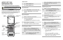
ASTRO® XTS™ 4000 Digital Portable Radio, Quick Reference Card Radio On/Off Product Safety and RF Exposure Compliance ! Caution Before using this product, read the operating instructions for safe usage contained in the Product Safety and RF Exposure booklet enclosed with your radio. ATTENTION! This radio is restricted to occupational use only to satisfy FCC RF energy exposure requirements.
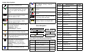
Display Status Symbols Receiving an individual call. Received signal strength for the current site (trunking only). The more bars in the symbol, the stronger the signal.
m ASTRO ® XTS™ 4000 Digital Portable Radio User Guide 6871618L01-C
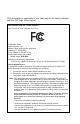
This declaration is applicable to your radio only if your radio is labeled with the FCC logo shown below. DECLARATION OF CONFORMITY Per FCC CFR 47 Part 2 Section 2.1077(a) Responsible Party Name: Motorola, Inc. Address: 8000 West Sunrise Boulevard Plantation, FL 33322 USA Phone Number: 1-800-927-2744 Hereby declares that the product: Model Name: XTS 4000 conforms to the following regulations: FCC Part 15, subpart B, section 15.107(a), 15.107(d) and section 15.
Product Safety and RF Exposure Compliance Before using this product, read the operating instructions for safe usage contained in the Product Safety and RF Exposure booklet C a u t i o n enclosed with your radio. ! ATTENTION! This radio is restricted to occupational use only to satisfy FCC RF energy exposure requirements.
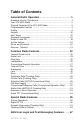
Table of Contents General Radio Operation . . . . . . . . . . . . . . . . . . . . . . . 1 Notations Used in This Manual ......................................................... 1 Your XTS 4000 Radio ....................................................................... 2 Physical Features of the XTS 4000 Radio ........................................ 3 Programmable Controls .................................................................... 3 Display ......................................................
Automatic Registration Service (ARS) .............................................67 ARS User Login Feature .................................................................69 Text Messaging ................................................................................74 Helpful Tips . . . . . . . . . . . . . . . . . . . . . . . . . . . . . . . . . 87 Radio Care ......................................................................................87 Service ...............................................
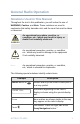
General Radio Operation Notations Used in This Manual Throughout the text in this publication, you will notice the use of WARNING, Caution, and Note. These notations are used to emphasize that safety hazards exist, and the care that must be taken or observed. An operational procedure, practice, or condition, etc., which may result in injury or death if not carefully observed. ! WARNING An operational procedure, practice, or condition, etc.
General Radio Operation Physical Features of the XTS 4000 Radio Table 1: Physical Features No. Feature 1 Antenna 2 Home Button 3 Volume Rocker 4 PTT (Push-to-Talk) Button 5 External Display 6 External Audio Speaker 7 Battery 8 Internal Audio Speaker 9 Internal Display No. Feature 10 Menu Select Buttons 11 Power Button 12 Data Button 13 4-Way Navigation Button 14 Keypad 18 Audio Jack 19 CE Connector 21 Microphone Note: Do not block or cover the microphone when talking through the radio.
General Radio Operation Table 2: Programmable Features Feature Page Feature Page Feature Page Call Alert 46 PL Defeat 27 Selective Call 45 Call Response 39 Private Call 42 Site Lock/ Unlock 65 Channel 20 Repeater/Direct 53 Site Search 66 Dynamic Priority 38 Reprogram Request 61 Speaker 26 Emergency 29 Ring Style 25 Status 51 Dim 5 Scan List Programming 34 TX Power Level 22 Monitor 21 Scan On/Off 37 Volume Set 19 Nuisance Delete 37 Secure/Clear 55 Zone 20
General Radio Operation Adjusting the Display Brightness Press the preprogrammed Dim button or access this feature through the menu to change the display brightness to one of three levels. • Off to high • High to medium • Medium to off The level of brightness will remain on for a preprogrammed time before it turns off automatically, or you can turn it off immediately by pressing the Dim button again.
General Radio Operation Table 3: Status Symbols (Continued) Icon Description Direct • Displayed = You are talking directly to another radio, not through a repeater, during conventional operation only. • Not Displayed = You are talking through a repeater Loudspeaker • Audio is routed to the radio’s external speaker. • Audio is routed to the radio’s internal speaker. Monitor (Carrier Squelch) The selected channel is being monitored during conventional operation only.
General Radio Operation Table 3: Status Symbols (Continued) Icon Description Tx Indicates the radio is transmitting data. Will not be displayed when the radio is sending a silent emergency alarm. Rx Indicates the radio is receiving data. Will not be displayed when the radio is sending a silent emergency alarm. Tx Power Level Indicates the transmission power is LOW. *PPP Link Establishment Indicates the subscriber is ready to receive data through a data cable.
General Radio Operation Menu Entry (Softkey) The bottom row of the display contains one to three menu entries (also known as softkeys). The menu entries allow you to select one of several menus to access the radio’s features. The menu entries are accessed through the Menu Select buttons. Menu Select Buttons The Menu Select buttons access the menu entries of features that have been activated by a qualified radio technician.
General Radio Operation Menu Entry Features Table 4: Menu Entries Menu Entry Page Menu Entry Page Private Call / Selective Call Call 43/46 Password Pswd 23 Channel Selection Chan 20 TX Power Level Pwr 22 Repeater/Direct Dir 53 Rekey Request Reky 59 Key Zeroization/ Erase Eras 58 Reprogram Request Rpgm 61 Key 56 Scan On/Off Scan 37 Keyset Selection Kset 57 Site Lock/Unlock Site 65 Radio Lock Logf 24 Loudspeaker Spkr 26 Text Select Name 34 Status Call Sts 51
General Radio Operation Data Button A CPS programmable button that can be programmed to launch specific data features such as text messaging and location service. Programmable Buttons The programmable buttons can be programmed for features as specified in the CPS. These buttons provide you convenient access to commonly used radio features. 4-Way Navigation Button This button is used to scroll through the radio’s lists or items in the display, or both.
General Radio Operation Table 5: Keypad Characters Number of times the key is pressed Key 1 2 3 4 5 6 7 0 0 ( ) < > 1 1 & % 2 A B C 2 a b c 3 D E F 3 d e f 4 G H I 4 g h i 5 J K L 5 j k l 6 M N O 6 m n o 7 P Q R S 7 p q 8 T U V 8 t u v 9 W X Y Z 9 w x * * / + - = # # .
General Radio Operation Alert Tones An alert tone is a sound or group of sounds. Your radio uses alert tones to inform you of your radio’s conditions. The following table lists these tones and when they occur. Table 6: Alert Tones You Hear Tone Name Invalid Key-Press Heard When wrong key is pressed. Radio Self-Test When radio fails its power-up self Short, Fail test. Low-Pitched Reject When unauthorized request is Tone made. Time-Out Timer Four seconds before time out.
General Radio Operation Table 6: Alert Tones (Continued) You Hear Tone Name Valid KeyPress Heard When correct key is pressed. Radio Self-Test When radio passes its power-up Pass self test. Short, MediumPitched Tone Long, MediumPitched Tone A Group of MediumPitched Tones Clear Voice At beginning of a non-coded communication. Priority Channel Received When activity on a priority channel is received. Emergency Alarm Entry When entering the emergency state.
General Radio Operation Table 6: Alert Tones (Continued) You Hear Tone Name Short, Low-Battery High-Pitched Chirp Tone (Chirp) Ringing Gurgle 14 Heard When battery is below preset threshold value. Happens only during transmit mode or standby mode. Fast Ringing When system is searching for target of Private Call. Enhanced Call Sent When waiting for target of Private Call to answer the call. Phone Call Received When a land-to-mobile phone call is received.
General Radio Operation Standard Accessories Battery To avoid a possible explosion: ! • DO NOT replace the battery in any area labeled “hazardous atmosphere”. • DO NOT discard batteries in a fire. WARNING Charging the Battery The Motorola-approved battery shipped with your radio is uncharged. Prior to using a new battery, charge a 630mAh Standard Li-Ion Battery for a minimum of 5 hours to ensure optimum capacity and performance.
General Radio Operation Zones and Channels A zone is a grouping of channels. A channel is a group of radio characteristics, such as transmit/receive frequency pairs. Before you use your radio to receive or send messages, you should select the zone and channel. Select a Zone 1 Press 2 Press to find Zone. directly below Zone. The current zone blinks and the channel name, does not blink. 3 Press to find the zone you want. 4 Press directly below Sel to confirm the displayed zone and channel.
General Radio Operation Receive / Transmit Radio users who switch from analog to digital radios often assume that the lack of static on a digital channel is an indication that the radio is not working properly. This is not the case. Digital technology quiets the transmission by removing the “noise” from the signal and allowing only the clear voice or data information to be heard. This section emphasizes the importance of knowing how to monitor a channel for traffic before keying up to send a transmission.
Common Radio Features Transmit Power Level This feature lets you select the power level at which your radio will transmit. The radio will always turn on to the default setting. This feature must be preprogrammed by a qualified radio technician. • Select Low for a shorter transmitting distance and to conserve power. • Select High for a longer transmitting distance. Select Power Level 1 Press 2 Press 22 to find Pwr. directly below Pwr to toggle between Low and High.
Common Radio Features Radio Lock This feature changes your radio to a more robust security system that protects the use of the secure encryption keys. If this feature is enabled in your radio by a qualified radio technician, when you turn the radio on, you see Radio locked. Unlock Your Radio 1 Enter your numeric password. Note: • Secure-equipped radios — 6 to 8 characters. • Clear radios — 0 to 8 characters. If you make a mistake, press 2 to backspace.
Common Radio Features 5 Enter the new password. 6 Press 7 Re-enter the new password. 8 Press directly below Sel. directly below Sel. The password is updated. Note: • If the two passwords do not match, repeat steps 5 through 8. • If you enter three incorrect old passwords, the radio exits the password feature. You cannot access this feature again until you turn the radio off and on.
Common Radio Features Ring Style This feature allows you to select the type of alert when your radio receives incoming individual calls or pages. Ring Style Icon Description Vibrate and Ring Radio vibrates and rings when incoming individual calls and pages are received. Vibrate Only Radio vibrates when incoming calls and pages are received. Ring Only Radio rings when incoming calls and pages are received. Silent Radio is in silent mode.
Common Radio Features Loudspeaker The external speaker allows you to share your call with your group. Change to External Speaker 1 Press to find Spkr. 2 Press directly below Spkr to toggle the audio to the external speaker. The icon is shown on the display. Note: When the earpiece or headset is plugged into the audio jack, the external speaker will not work. 3 Press directly below Spkr again to route the audio back to the internal speaker.
Common Radio Features Conventional Squelch Operation Digital Options One or more of the following options may be programmed in your radio. Consult your service technician for more information. This option Will allow you to hear Digital Carrier-Operated Squelch (COS) any digital traffic. Normal Squelch any digital traffic having the correct Network Access Code (NAC). Selective Switch any digital traffic having the correct network access code and correct talkgroup.
Common Radio Features Time-out Timer The time-out timer turns off your radio’s transmitter. The timer is set for 60 seconds at the factory, but it can be programmed from 0 to 7.75 minutes (465 seconds) by a qualified radio technician. 1 Hold down the PTT button longer than the programmed time. You will hear a short, low-pitched warning tone, the transmission will cut-off. 2 Release the PTT button. 3 Press the PTT to re-transmit. The time-out timer restarts.
Common Radio Features Emergency If the top (orange) button is programmed to send an emergency signal, then this signal overrides any other communication over the selected channel. Your radio can be programmed for the following: • Emergency Alarm • Emergency Call • Emergency Alarm with Emergency Call • Silent Emergency Alarm Consult a qualified radio technician for emergency programming of your radio.
Common Radio Features Send an Emergency Call This type of dispatch gives your radio priority access on a channel. The radio operates in the normal dispatch manner while in Emergency Call, except, if enabled, it will return to one of the following: • Tactical/Non-Revert — You talk on the channel you selected before you entered the emergency state. • Non-Tactical/Revert — You talk on a preprogrammed emergency channel. The emergency alarm is sent on this same channel. 1.
Special Radio Features Site View and Change You can view the number of the current site or force your radio to change to a new one. View the Current Site Press the preprogrammed Site Search button. The display momentarily shows the name of the current site and its corresponding received signal strength indicator (RSSI). (See Table 3 on page 5.) OR If the radio is scanning for a new site, you momentarily see Scanning site. Change the Current Site Press and hold down the preprogrammed Site Search button.
ARS User Login and Text Messaging Features Automatic Registration Service (ARS) Automatic Registration Service feature provides an automated data application registration for the radio. When you turn on the radio, the device automatically registers with the server. Data applications within the fixed network can determine the presence of a device on the system and send data to the device. For example: Text Messaging Service (TMS).
ARS User Login and Text Messaging Features Table 8: TMS Menu Options Menu Options Description/ Function Inbx This is used to store new incoming messages or messages that you have received. Inbox can hold up to 30 messages. Comp This menu option brings you to the compose screen. Drft This is used to store all saved messages or messages that are to be sent at a later time. Draft folder can hold up to 10 messages. Sent This is used to store the messages that you have already sent.
ARS User Login and Text Messaging Features Menu Options Description/ Function Rqrp This menu option is used to toggle on/off the “Request reply” flag for an outgoing message. Curr This menu option is used to delete the current selected message. All This menu option is used to delete all the messages in the current message inbox. Table 9: TMS Status Symbols Symbol Indication Priority Message This icon is displayed • when “Priority” is toggled on before sending the message.
ARS User Login and Text Messaging Features Symbol Indication Message Sent This icon is displayed if the selected message has been successfully sent. Message Unsent This icon is displayed if the selected message was not successfully sent. Read Message This icon is displayed when the selected message in the Inbox has been read. Unread Message The selected message in the Inbox folder has not been read. Message Index This icon indicates the index of the current message the user is viewing.
ARS User Login and Text Messaging Features Receive a Message When you receive a message, a momentary text, New msg appears on the display along with a new message icon. If inbox is full, the message icon will be blinking. New Msg Prog User TMS To View Message from the Inbox 1 Access TMS (Launch TMS). 2 Press Inbx. directly below User 00000004 Inbx Comp Drft 3 The Inbox screen appears. The first message in the list is displayed. Inbox can hold up to 30 messages.
ARS User Login and Text Messaging Features 4 Scroll to the message you want to read by pressing the button. Note: If the message fills more than one screen, scroll to read it by pressing 5 or or button. To delete the message, press below Del. See “Delete a Message” on page 85. for further details.
ARS User Login and Text Messaging Features Compose a New Text Message 1 Press below Comp to compose a new message. List or new The Compose Message Screen appears. List or New option appears on the display. New List Back 2 Press below New to type a new message. A blinking cursor appears on the display indicating point of input. 3 Writing Text Type your message using the keypad. Press the key labeled with the desired character, once for the first character, twice for the second, and so on.
ARS User Login and Text Messaging Features Table 10: Keypad Characters Number of times the key is pressed (in normal mode) Key 1 2 3 4 5 6 7 0 0 or press and hold to toggle between normal text entry mode, uppercase mode and num lock mode. 1 1 . , ? ! ; @ _ - *# & $ / + = \ “ ‘ ( ) 1* 1 .
ARS User Login and Text Messaging Features Press or to scroll through the address list. OR Use direct address entry via multi-tap. 5 Append a Priority Message or Request Receipt Before sending your message, you can append a priority message or a Addr: request receipt to your message. Press below Impt to toggle on/ off a “Priority” flag for an outgoing message. A ‘Priority’ flag icon is displayed at the top of the screen when it is toggled on.
ARS User Login and Text Messaging Features 6 When an address has been appended to the outgoing message, press the PTT button to send your message. OR Press below Save to save your message for sending at a later time. The message will be saved in the “Draft folder”. See “To Access the Draft Folder” on page 86. for further details. Send a Predefined Message Quick Text Messages are messages that are predefined and usually consist of messages that are used most frequently.
ARS User Login and Text Messaging Features Edit a Quick Text Message 1 Press below Edit to edit a quick text message. QT 01/01 I am late today The Editing Screen appears. A blinking cursor appears at the end of the predefined text. Edit your message using the keypad. Addr Save Back 2 Press below Save to save the edited changes. The message is saved in the Draft folder. 3 When an address has been appended to the outgoing message, press the PTT button to send the edited message.
ARS User Login and Text Messaging Features Delete a Message 1 From the Inbox, Draft or Sent screen, scroll to select a message for deletion. 2 After selecting a message, press below Del. The display shows 2 delete options. Inbox 01/01 From : User1 Hello Press below Curr to delete only the current message. OR Press below All to delete all messages. Curr All Back OR Press 3 below Back to return to previous menu. When you select to delete all messages,a confirmation screen appears.
ARS User Login and Text Messaging Features To Access the Draft Folder The Draft folder stores the messages that were saved previously. Newest saved message is appended at the bottom of the list. Draft folder can hold up to 10 messages. The oldest draft in the folder is deleted when the 11th message comes in. 1 Press below Drft. The Draft screen appears. The first draft in list is displayed. 2 Draft 01/01 I have a meeting at 9am tomorrow Press or to scroll through the list of drafts.
Helpful Tips Radio Care RF Dust Cover Vent Port • The XTS 4000 radio casting has a RF Dust cover. Never remove this cover as this would create leak paths into the radio. • Never insert any objects into the vent port, such as needles, tweezers, or screwdrivers. This could create leak paths into the radio.
Helpful Tips • If the radio battery contact area has been submerged in water, dry and clean the radio battery contacts before attaching a battery to the radio. Otherwise, the water could short-circuit the radio. • If the radio has been submerged in water, shake the radio well so that any water that may be trapped inside the speaker grille and microphone port can be removed. Otherwise, the water will decrease the audio quality of the radio. • Do not disassemble the radio.
Helpful Tips Handling • Do not pound, drop, or throw the radio unnecessarily. Never carry the radio by the antenna. • Avoid subjecting the radio to an excess of liquids. Do not submerge the radio. • Avoid subjecting the radio to corrosives, solvents or spirits. • Do not disassemble the radio. • Keep the accessory-connector cover in place until ready to use the connector. Close the cover immediately once the accessory has been disconnected.
Helpful Tips Charging the Battery Motorola batteries are designed specifically to be used with a Motorola charger. Charging in non-Motorola equipment may lead to battery damage and void the battery warranty. Motorola-authorized battery chargers may not charge batteries other than the ones listed on page 94. The battery should be at about 25°C (77°F) (room temperature), whenever possible, for charging. The acceptable charge temperature range is 0°C to 45°C.
Helpful Tips Fuel Gauge Symbol The radio indicates the current battery charge level through a fuel gauge symbol. Refer to the table below for more information. Fuel Gauge External Internal Indicator Indicator Charge Level 60% - 100% 40% - 59% 20% - 39% 6% - 19% 0% - 5% Battery Recycling and Disposal Lithium Ion (Li-Ion) rechargeable batteries can be recycled. However, recycling facilities may not be available in all areas. Under various U.S.
Helpful Tips information concerning recycling options for consumers, businesses, and governmental agencies. Symbol Definition Important safety important follows. Do not dispose of your battery or mobile device in a fire. Your battery or mobile device may require recycling in accordance with local laws. Contact your local regulatory authorities for more information. Do not throw your battery or mobile device in the trash. Li Ion BATT 92 Your mobile device contains an internal lithium ion battery.
Accessories Motorola provides the following approved accessories to improve the productivity of your XTS 4000 portable two-way radio. Motorola do not certify the use of other Nextel type accessories with this radio. Antennas Antennas for different frequencies are indicated by the color of the straw. Please refer to the following picture to identify the straw on the antenna. Straw The straw color for each antenna is given in the following table.
Accessories Batteries and Battery Accessories NNTN6944_ 630 mAh Standard Li-Ion Battery PMNN4083_ 1260 mAh Standard Li-Ion Battery Carry Accessories Belt Clips NNTN6945_ Plastic Belt Clip NNTN6946_ Leather Belt Clip Chargers NNTN6938_ XTS 4000 Charger US 110V AC NNTN6937_ XTS 4000 Charging Cradle NNTN6939_ XTS 4000 Charger 12V Vehicular Headsets and Earpieces NNTN5006BP Headset Earbud with PTT NNTN5211_ 2-Wire Surveillance Kit 94