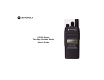
M CP185 CP185 Series Two-Way Portable Radio User’s Guide
CONTENTS Safety . . . . . . . . . . . . . . . . . . . . . . . . . . . . . iii Radio Overview . . . . . . . . . . . . . . . . . . . . . . 1 LED Colors . . . . . . . . . . . . . . . . . . . . . . . . . . 3 LCD Display and Icons . . . . . . . . . . . . . . . . . 4 Programmable Buttons . . . . . . . . . . . . . . . . . . 5 Getting Started . . . . . . . . . . . . . . . . . . . . . . . 7 Attaching and Removing the Antenna . . . . . 7 Attaching and Removing the Battery . . . . . .
COMPUTER SOFTWARE COPYRIGHTS COMPUTER SOFTWARE COPYRIGHTS The Motorola products described in this manual may include copyrighted Motorola computer programs stored in semiconductor memories or other media. Laws in the United States and other countries preserve for Motorola certain exclusive rights for copyrighted computer programs, including, but not limited to, the exclusive right to copy or reproduce in any form the copyrighted computer program.
SAFETY PRODUCT SAFETY AND RF EXPOSURE COMPLIANCE ! Caution Before using this product, read the operating instructions for safe usage contained in the Product Safety and RF Exposure booklet enclosed with your radio. ATTENTION! This radio is restricted to occupational use only to satisfy FCC RF energy exposure requirements.
SAFETY Notes: English iv
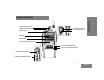
RADIO OVERVIEW 9 Accessory Connector 10 Programming Port 2 On/Off and Volume Knob 3 LED Indicator RADIO OVERVIEW 1 Channel Selector Knob CP185 4 Speaker 5 Microphone 6 Liquid Crystal Display (LCD) 11 Front Left/Right Buttons 12 Front Programmable Buttons 7 Push-to-Talk (PTT) Button 8 Side Programmable Buttons 1 English English
1. Channel Selector Knob RADIO OVERVIEW Used to select channels in normal radio operation mode. 2. On/Off and Volume Knob Turn the ON/OFF/Volume Control knob clockwise to turn the radio ON. Turn the ON/OFF/Volume Control knob counterclockwise to turn the radio OFF. Turn this knob clockwise to increase the volume. Turn this knob counterclockwise to decrease the volume. 3. LED Indicator Indicates radio transmit, receive, scan and monitor status. Refer to "LED Colors" on page 3 for more information. 4.
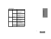
LED COLORS LED Color Amber Red State Indication Illuminated Radio is transmitting in normal mode. Radio is transmitting in scrambling mode. Normal Blinking Radio is receiving in normal mode. Channel is busy. Radio passed self test during powering up. Illuminated Monitor activated. Permanent Sticky Monitor activated. Normal Blinking Radio is in active scan mode. Radio is receiving in scrambling mode. Normal Blinking Radio is transmitting in normal mode while battery is low.
RADIO OVERVIEW LCD Display and Icons Displays selected channel, programming parameters, status messages and any error or information messages. LCD Indicator English Description Description Function Programming Mode Indicator Illuminates when radio is in Programming Mode. Keypad Lock Indicator Illuminates when keypad is locked. Battery Level Indicator Shows remaining charge in battery based on how many bars (1 – 3) are displayed. Blinks when the battery is low.
Programmable Buttons Button The programmable buttons consist of: Side Programmable Button 1 • Side Programmable Button 2 • Front Programmable Button 1 • Front Programmable Button 2 • Locks or unlocks all buttons except PTT, Side Programmable Button 1, Side Programmable Button 2, Channel Selector Knob and ON/OFF/ Volume Knob. Monitor Monitors the channel for any activity as long as the button is pressed. Nuisance Removes unwanted channel(s) temporarily from Channel Delete scan list during scan.
RADIO OVERVIEW Button Function Scrambling Enable/Disable Enables or disables scrambling feature for the selected channel. Volume Set A programmable button used to control the audio level. The button emits a continuous tone to indicate the current volume level. To change volume level, turn the volume knob to the desired level while pressing the programmable button. VOX Enables or disables VOX feature for the selected channel.
GETTING STARTED To Attach Antenna Attaching and Removing the Antenna 1. Fasten the antenna to the radio by placing the threaded end of the antenna into the Antenna Connector. 2. Rotate the antenna clockwise until tight. To Remove Antenna Threaded End of Antenna 1. Turn the antenna in a counter-clockwise direction until it disengages from the radio.
Attaching and Removing the Battery Grooves To Attach Battery 1. Fit the battery slots with the grooves on the radio. 2. Slide the battery upwards until a click is heard. GETTING STARTED To Remove Battery Battery Latch Battery Slots English 8 1. Slide the battery latch away from the radio. 2. Slide the battery downwards. 3. Pull the battery away from the radio.
Attaching and Removing the Belt Clip Release Tab Mounting Grooves To Attach Belt Clip 1. Align mounting rails of the belt clip with the grooves of the radio. 2. Slide the belt clip downwards until it clicks into place. To Remove Belt Clip Safely insert a flat tool between the release tab and the back surface of the radio. 2. Lift the release tab. 3. Slide the belt clip upwards. GETTING STARTED 1.
Charging the Battery 5. Turn the radio OFF before charging the battery. Insert a battery, or a radio with a battery into the charger’s pocket by: a) Aligning the groove on each side of the battery with the corresponding raised rail on each side of the charger pocket OR b) Pressing the battery towards the rear of the pocket OR c) Sliding the battery into the charger pocket, ensuring complete contact between the charger and battery contacts. 6.
LED Color Charging Status Charging Blinking Red Battery Fault Solid Green Charge Complete Blinking Green Trickle Charging Single Green Blink Power On Blinking Yellow Waiting to Charge GETTING STARTED Solid Red Note: To get maximum use from a new battery, charge it overnight (12 to 16 hours) before using the battery for the first time. The typical time needed to completely charge the discharged battery is estimated within 2.5 to 5 hours depending on its cell chemistry.
SCAN Scan allows you to monitor multiple channels and receive calls that are transmitted on them. Two types of scan are supported: Normal Scan and Priority Scan. Normal Scan searches all channels sequentially in the radio’s scan list, whereas Priority Scan allocates 50% of the scanning time to the Priority Channel (the first channel in the designated scan list). Start Ch. 2 Ch. 14 Home Ch. 16 Ch. 15 Ch. 2 Ch. 1 Ch. 3 Priority Scan Channel 1 Prioritized Ch. 1 Home SCAN Ch. 4 Normal Scan Ch.
VOICE OPERATED TRANSMIT (VOX) VOICE OPERATED TRANSMIT (VOX) When the VOX headset/microphone is connected, your radio may be used in hands-free operation. To start the VOX feature: 1. Connect the VOX headset to the accessory connector of the radio. Make sure the radio is turned OFF before connecting the VOX accessory. 2. Turn the radio ON. To disable the VOX feature: 1. Press the PTT button on the radio. This allows you to use the VOX headset, but you must press the radio PTT to transmit.
VOICE INVERSION SCRAMBLING VOICE INVERSION SCRAMBLING Your radio has the Voice Inversion Scrambling feature which gives you an extra layer of privacy. This scrambling function is implemented via a frequency inversion in analog mode using two standard codes (3.29 KHz and 3.39 KHz). To Enable and Disable the Scrambling Mode Configure one of the programmable buttons for Scrambling Mode. Press this button to enable or disable the function.
FRONT PANEL PROGRAMMING MODE This mode allows you to change the feature parameters to enhance the use of your radio. Note: This feature is only supported by certain models. Assessing Front Panel Programming Mode Parameters Press the or to scroll through the parameters for each menu or sub-menu item, or Press the PTT button to select menu or sub-menu item, or Entering Front Panel Programming Mode If your radio is turned ON, turn it OFF. Press and hold the side programmable button 1, and turn your radio ON.
1st Level Sub-Menu Main Menu BCKLIGHT (Backlight) English Setting Remarks AUTO TOGGLE Selecting AUTO causes the backlight to automatically extinguish, if there is no keypress for more than 5 seconds. Pressing the Backlight button again prolongs illumination time. Selecting TOGGLE allows the Backlight button toggle to control the ON/OFF status of the backlight. SAVER (Battery Saver) OFF NORMAL ENHANCED Helps to extend the battery life.
Main Menu ACCESORY (Accessory) TONE VOL (Alert Tone Volume) 1st Level Sub-Menu 2nd Level Sub-Menu Setting Remarks +2 +1 0 -1 -2 Allows you to adjust the external speaker loudness when accessories are connected to radio. +2 will set the external speaker gain to maximum level and -2 will set the external speaker gain to minimum level. MIC GAIN (External Microphone Gain) +2 +1 0 -1 -2 Allows you to adjust the external microphone sensitivity when accessories are connected to radio.
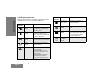
Main Menu FRONT PANEL PROGRAMMING MODE CHANNEL English 1st Level Sub-Menu 2nd Level Sub-Menu Settings Remarks RX PL (Receive TPL/ DPL) CH-001 … CH-099 CSQ (Carrier Squelch) TPL 067.0… TPL 254.1 TPL1 TPL2 TPL3 DPL 023… DPL 754 This is the TPL or DPL code that the channel will use to unsquelch the received signal. CSQ indicates that radio operates in carrier squelch mode. Press Left Arrow Button or Right Arrow Button to select the desired TPL/DPL.
Main Menu 1st Level Sub-Menu CHANNEL (Cont’d) PRIME CH (Prime Channel) SCAN LIST 1 (Scan List 1) 2nd Level Sub-Menu Settings Remarks The channel that you wish to spend most of your time monitoring. The radio will always switch back to the Prime Channel if it is idle for more than the preprogrammed hang-time in other channels. . 01-XXX 02-XXX … 15-XXX 16-XXX ___ 001 … 099 Allows you to set scan list 1 members. “XXX “denotes the selected scan list member.
FRONT PANEL PROGRAMMING MODE Notes: English 20
The following information in the tables are to guide the user to select the appropriate TPL (Tone Private Line) or DPL (Digital Private Line) codes so that they can expand usage of the frequency. TPL Frequency Table 1: TPL Frequency Equivalent PL Code Motorola Code 67.0 XZ 001 69.3 WZ 002 71.9 XA 003 74.4 WA 004 77.0 XB 005 79.7 WB 006 82.5 YZ 007 85.4 YA 008 88.5 YB 009 91.5 ZZ 010 94.
TPL AND DPL FREQUENCIES AND CODES Table 1: TPL Frequency TPL Freq (Hz) Equivalent PL Code Motorola Code 186.2 7Z 031 192.8 7A 032 203.5 M1 033 206.5 8Z 034 210.7 M2 035 218.1 M3 036 225.7 M4 037 229.1 9Z 038 233.6* M5 039 241.8 M6 040 250.3 M7 041 254.1* 0Z 042 TPL1* – TPL1 TPL2* – TPL2 TPL 3* – TPL3 Note: The TPL Frequencies marked with an asterisk (*) are not part of the 39 standard EIA/TIA-603 CTCSS Code Frequency.
Table 2: DPL Codes Table 2: DPL Codes DPL Code Motorola Code 023 043 025 044 026 045 031 046 032 047 043 048 047 049 051 050 054 051 065 052 071 053 072 054 073 055 074 056 114 057 115 058 116 059 DPL Code Motorola Code 125 060 131 061 132 062 134 063 143 064 152 065 155 066 156 067 162 068 165 069 172 070 174 071 205 072 223 073 226 074 243 075 244 076 245 077 23 TPL AND DPL FREQUENCIES AND CODES DPL Codes English
TPL AND DPL FREQUENCIES AND CODES English Table 2: DPL Codes Table 2: DPL Codes DPL Code Motorola Code DPL Code Motorola Code 251 078 423 096 261 079 431 097 263 080 432 098 265 081 445 099 271 082 464 100 306 083 465 101 311 084 466 102 315 085 503 103 331 086 506 104 343 087 516 105 346 088 525(*) 106 351 089 532 107 364 090 546 108 365 091 565 109 371 092 606 110 411 093 612 111 412 094 624 112 413 095 627 113 24
DPL Code Motorola Code 631 114 632 115 645(*) 116 654 117 662 118 664 119 703 120 712 121 723 122 731 123 732 124 734 125 743 126 754 127 TPL AND DPL FREQUENCIES AND CODES Table 2: DPL Codes Note: The codes marked with an asterisk (*) are not part of the 83 standard EIA/TIA-603 codes.
MOTOROLA LIMITED WARRANTY FOR THE UNITED STATES AND CANADA WARRANTY What Does this Warranty Cover? English Subject to the exclusions contained below, Motorola, Inc.
Exclusions 27 WARRANTY Normal Wear and Tear. Periodic maintenance, repair and replacement of parts due to normal wear and tear are excluded from coverage. Batteries. Only batteries whose fully charged capacity falls below 80% of their rated capacity and batteries that leak are covered by this limited warranty. Abuse & Misuse. Defects or damage that result from: (a) improper operation, storage, misuse or abuse, accident or neglect, such as physical damage (cracks, scratches, etc.
Communication Services. Defects, damages, or the failure of Products, Accessories or Software due to any communication service or signal you may subscribe to or use with the Products Accessories or Software is excluded from coverage. Software WARRANTY Products Covered Software. Applies only to physical defects in the media that embodies the copy of the software (e.g. CD-ROM, or floppy disk). Length of Coverage Ninety (90) days from the date of purchase. Exclusions Software Embodied in Physical Media.
SOFTWARE COPYRIGHT NOTICE PATENT NOTICE The Motorola products described in this manual may include copyrighted Motorola and third party software stored in semiconductor memories or other media. Laws in the United States and other countries preserve for Motorola and third party software providers certain exclusive rights for copyrighted software, such as the exclusive rights to distribute or reproduce the copyrighted software.
WARRANTY Notes: English 30
ACCESSORIES BATTERIES The following accessories parts are compatible with model number CP185.
AUDIO ACCESSORIES CHARGERS AND POWER ADAPTERS Motorola Part Number Description PMLN5228_ Tri-Chem Single Unit Charger Base PMLN5398_ Single Unit Charger Base with US 2-Pin Switch Mode Power Supply 2571586S14 EPNN9288_ 110V, 10.
AUDIO ACCESSORIES Motorola Part Number Description MISCELLANEOUS Motorola Part Number Description MOTOROLA Branded HLN9844_ Spring Action Belt Clip (2 inch) PMMN4001_ Earset with Microphone and PTT PMLN5334_ Protective Leather Case PMMN4013_ Remote Speaker Microphone with Ear Jack PMMN4029_ Remote Speaker Microphone with IP57 Rating RLN6230_ High Noise Kit, Black (Includes Foam Earplugs with Acoustic Tube) RLN6231_ High Noise Kit, Beige (Includes Foam Earplugs with Acoustic Tube) RLN6232_
ACCESSORIES Notes: English 34
MOTOROLA and the Stylized M Logo are registered in the US Patent & Trademark Office. All other product or service names are the property of their respective owners. © 2008 by Motorola, Inc. All rights reserved.