“DRAFT” Developer’s Guide iO200 OEM Module Module Description Version: 01.00-D06 Date: Nov 28, 2004 © Motorola Israel Ltd., 2004 A subsidiary of Motorola Inc. All rights reserved. Documentation Copyrights No duplication or distribution of this document or any portion thereof shall take place without the express written permission of Motorola.
Table of Contents 1. 2. 3. 4. 5. Introduction......................................................................................................................................................................... 8 1.1. USING THIS GUIDE................................................................................................................................................ 8 1.2. PURPOSE ..............................................................................................................
5.9. Audio Interface........................................................................................................................................................ 22 5.10. Nominal Audio Signal............................................................................................................................................. 22 5.11. Audio Processing and Control.................................................................................................................................
10.1. Gemini Processor Architecture................................................................................................................................ 51 10.2. General Definitions ................................................................................................................................................. 51 10.3. Initialization......................................................................................................................................................
Figures FIGURE 1. FIGURE 2. FIGURE 3. FIGURE 4. FIGURE 5. FIGURE 6. FIGURE 7. FIGURE 8. FIGURE 9. FIGURE 10. FIGURE 11. FIGURE 12. FIGURE 13. FIGURE 14. FIGURE 15. FIGURE 16. FIGURE 17. FIGURE 18. FIGURE 19. FIGURE 20. FIGURE 21. FIGURE 22. FIGURE 23. FIGURE 24. FIGURE 25. FIGURE 26. FIGURE 27. FIGURE 28. FIGURE 29. FIGURE 30. FIGURE 31. FIGURE 32. FIGURE 33. FIGURE 34. FIGURE 35. FIGURE 36. FIGURE 37. FIGURE 38. FIGURE 39. FIGURE 40. FIGURE 41. FIGURE 42. FIGURE 43. FIGURE 44. FIGURE 45. FIGURE 46.
FIGURE 52. FIGURE 53. FIGURE 54. FIGURE 55. FIGURE 56. FIGURE 57. FIGURE 58. FIGURE 59. FIGURE 60. FIGURE 61. FIGURE 62. FIGURE 63. FIGURE 64. FIGURE 65. FIGURE 66. FIGURE 67. FIGURE 68. FIGURE 69. FIGURE 70. FIGURE 71. FIGURE 72. FIGURE 73. FIGURE 74. FIGURE 75. FIGURE 76. FIGURE 77. FIGURE 78. FIGURE 79. FIGURE 80. FIGURE 81. FIGURE 82. FIGURE 83. FIGURE 84. FIGURE 85. FIGURE 86. FIGURE 87. FIGURE 88. FIGURE 89. FIGURE 90. FIGURE 91. FIGURE 92. FIGURE 93. FIGURE 94. FIGURE 95. FIGURE 96. FIGURE 97.
Tables TABLE 1 INTEGRATOR’S TASKS .............................................................................10 TABLE 2 PARTS AND TOOLS REQUIREMENTS .....................................................15 TABLE 3 MODULE INPUT VOLTAGE SPECIFICATIONS.........................................19 TABLE 4 IO200 CURRENT CONSUMPTION.............................................................20 TABLE 5 MAIN CONNECTOR LINES ........................................................................
1. Introduction 1.1. USING THIS GUIDE This guide presents critical research and development issues affecting the design and development of products incorporating the Motorola io200 800/900MHz iDEN Integrated Wireless Modem, used in North America, Asia, Africa and Europe. The purpose of this document is to describe the technical details needed to integrate io200 Data Module into a host device.
2. GENERAL NOTICES 2.1. Safety Notice - ATTENTION This iDEN iO200 Module is restricted to Occupational use to satisfy FCC RF energy exposure requirements. This radio device is not authorized for general population, consumer or similar use. The integrator shall be aware that after integrating this module and connecting it to an antenna and DC power supply, the integrated device shall be treated as a Two-Way Radio.
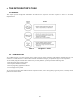
3. THE INTEGRATOR'S TASK 3.1.GENERAL This chapter provides background information and indicates the objectives and tasks required to achieve a successful implementation. Table 1 Integrator’s Tasks 3.2. INTRODUCTION As an OEM integrator, you must accurately choose where and how wireless technology will facilitate communication for your customers. You will also have to evaluate which technical considerations will give your product an edge over the competition.
3.3. PLANNING THE PRODUCT AND CREATING THE DESIGN To plan the product and create the design, perform the following steps: • Develop a usage model • Develop a message model • Define a service strategy • Define remote diagnostic functionality • Investigate and obtain regulatory approval 3.3.1. Developing a Usage Model The usage model answers the question, “How will the end product be used - will it be portable or mobile, how many hours a day will it be used, how many days a week?” and so on.
3.3.3. Defining a Service Strategy The service strategy determines whether the integrated modem is the cause of a user’s problem and sets a policy for keeping the end user operational during repair. The service strategy must consider all potential service situations and evaluate them in light of the usage model. You can create the service strategy jointly with Motorola. Contact your Motorola OEM sales representative for details.
3.3.5. Investigating and Obtaining Regulatory Approval It is your responsibility to obtain regulatory approval of products that integrate an io200 Integrated Wireless Modem. The specific details for achieving regulatory approval vary from country to country. Refer to “Regulatory Requirements”, page xvi ?, for further information. 3.4.
3.7.Selecting the Antenna Io200 is terminated by 50Ω; therefore, any antenna terminated by 50Ω will work with Io200. In order to protect the module from ESD discharge, the selected antenna must be rubber-coated.. Refer to “Antenna Considerations”, page 5.16, for further information. You are responsible for selecting a suitable antenna and submitting the final product to the network operator for certification. Note 3.8.
provider is down. To guarantee that the modem is located in an area with good coverage, and that an end-to-end loopback message is possible, your product needs a software application to perform the test. The most effective approach to field-testing is to include an installation test procedure as part of your standard software load. Motorola can recommend specific network information that you can obtain from the modem describing how to implement an endto-end loopback test.
Power Supply Dual Power Supply with 3-6V/2A and 12V/2A output supplies Commercial Items Oscilloscope Digital Volt Meter 900Mhz, digital storage Fluke 77 multimeter or equivalent Commercial Item Commercial Item 3.15. ENVIRONMENTAL ISSUES Io200 Integrated Wireless Modems are designed for a combination of easy serviceability and general robustness. These integrated modems are designed to be housed in an OEM host product.
4. MODEL DESCRIPTION 4.1. GENERAL This chapter provides an overview of Io200 integrated wireless modem. For model number, and specifications, refer to “Specifications”, on page 0. 4.2. INTRODUCTION Io200 is an iDEN modem providing circuit/packet data connectivity, interconnect and dispatch calls. The modem operates in iDEN 800 & 900 MHz networks using the iDEN Packet-switched and Circuit-switched Data protocols.
SIM Interface Connector (6-pin ZIF) RF Antenna Connector (coaxial) 4.5.INTEGRATOR’S KIT The Integrator's Kit includes the RF modem and Developers' Kit with installation SW via a CD or on-line. The kit has sufficient documentation for integrators to be able to successfully embed the device into their products. 4.6.MOUNTING The RF module includes 4 mounting holes.
5. DESIGN CONSIDERATIONS 5.1. GENERAL When integrating a wireless modem, internal connections and placements are critical for a successful implementation. Specific attention must be paid to the following support mechanisms: • Power supply considerations • Audio circuit considerations • Data port considerations • SIM card considerations • ESD considerations • Antenna considerations • Mechanical mounting • Desense control • GPS considerations Antennas must be separated by a minimum of 10 inches (25.4 cm).
Table 4 Mode IO200 Current Consumption Current Consumption 5.5. IO200 Output Voltage IO200 can supply DC voltage to accessories. Option_V+ line (Main Connector, pin #14) can drive 100mA @ 2.775VDC. Using this source for external RS232 transceiver ensures proper communication at correct voltage levels. 5.6.Turning the Unit On IO200 is powered from a single power supply in the range of 3.2 to 4.2 VDC. The unit will not power up automatically by connecting the power.
5.7. Turning the Unit OFF By ON/OFF pin There are two ways to turn off the unit: apply logic low, 0V, to ON/OFF pin or by “turn off” AT command. When IO200 is powered off by disconnecting the power to the unit, IO200 doesn’t deregister. SIM card might be damaged, and units containing IO200 that need to pass SIM card type approval tests will fail due to the SIM’s incorrect power off sequence.
5.8. AUDIO CIRCUIT CONSIDERATIONS IO200 supports both voice calls and data calls. IO200 module supports 3 modes of operation for voice communication: - Speakerphone - Headset - Raw For both received audio (speaker) and transmit audio (microphone), the module will utilize standard iDEN audio signal conditioning and processing. 5.9. Audio Interface The following figure shows the expected electrical interface for audio input and output signals: Host Terminal IO200 Module 100Ω 0.1uF Amp 100Ω 0.1uF 0.
Audio In The nominal differential Audio In signal shall have a level of: TBD mVrms in Speakerphone mode TBD mVrms in Headset mode TBD mVrms in Raw mode Audio Out The nominal differential Audio Out (volume 4) signal shall have a level of: TBD mVrms in Speakerphone mode TBD mVrms in Headset mode TBD mVrms in Raw mode 5.11.
RS-232 (8 wire) 0 1 Table 5 X main connector lines Notes: Default state is internally set by the modem via pull up resistors. To configure the modem for USB operation, the host terminal should only apply >4V to RTS1/USB_PWR pin. To configure the modem for RS-232 operation, the host terminal should only pull OPTION1 pin to ground level.
5.13. SIM CARD CONSIDERATIONS IO200 includes a SIM card driver, however it does not contain a SIM socket. SIM signals are routed to the 6-pin ZIF interface connector. The connector includes all the functionality required for SIM card operation. The SIM card socket must be located on the customer’s board and connected to IO200 interface connector as shown in Figure below. 5.14.
5.15. ESD CONSIDERATIONS Generally, ESD protection, up to 8KV, can be provided by using ceramic capacitors of 0.1uF or higher. The capacitors protect against ESD on all static lines, power and so on. The protection is performed inside IO200.IO200 also contains ESD Zener diode protection on almost all external lines; however, it is recommended to add protection on user PCB. For lines with high data rates, it is recommended to use Transguard with low capacitance. There are Transguards of 3pF or less.
Antennas for portable devices include the following designs: • Internal antenna (invisible or pull-up) • External antenna, removable and directly connected to the device • External, remote antenna 5.21.1.1. Internal Antenna (Invisible or Pull-up) This is the most difficult antenna design scenario. Despite greater physical constraints, an internal antenna must still provide a gain sufficient to meet network specifications.
Two tests must be performed on the antenna to ensure that it meets the requirements. For both tests, the antenna must be integrated in its final form. That is, the antenna must be mounted on a representative housing that includes all metal objects forming the ground plane or counterpoise. Antenna testing requires an experienced operator and an anechoic chamber, a GTEM cell, or approved open field site. Your Motorola OEM support representative can provide advice on this type of testing. 5.24.
6. AT COMMANDS 6.1. Data Services AT command set for data services (Circuit Data, Packet Data, and Facsimile) is described in iDEN Mobile Subscriber DTE/DCE Interface for Data Services document, Motorola Publication part number 6881129E10. You may download this document from: http://idenphones.motorola.com/iden/developer/developer_documentation.jsp 6.2.
7. GPS AT COMMANDS 7.1. GPS Request +WVGPS GPS Request +WVGPS commands set for Io200 OEM Module is described in Supplementary AT commands document section (GPS Request +WVGPS). Motorola Publication part number TBD. You may download this document from: TBD 7.2. GPS and Location Services GPS and Location Services commands set for Io200 OEM Module is described in Supplementary AT commands document section, GPS LES: AT+WVRLA Motorola Publication part number TBD.
8. SOFTWARE INTERFACE 8.1.
9. CALL SCENARIO 9.1. General This section describes interfaces usable by the TERMINAL to the io200 during any call type. The TERMINAL can use these interfaces whenever the io200 is unlocked: prior to call or during call. Responses will however vary based on the current state of the radio. 9.2. List Current Voice Calls The TERMINAL can gather information about any active calls from the io200.
9.3. Get Subscriber Numbers The TERMINAL can gather information about subscriber numbers used and stored in the io200. These numbers are: Voice for lines 1 and 2, Circuit Data, Private ID, Carrier IP, Primary Talkgroup ID, Secondary Talkgroup IDs (available in advanced feature models), Talkgroup Mode, and Group Affiliation. Figure 7.
9.4. Phone Activity Status The TERMINAL can query the io200 for its current activity status. This can be used to interrogate the io200 before requesting action from the io200. The following illustrates this interaction. Figure 8. Phone Activity Status TERMINAL BP (DL-TEL) 0 0 9.5. Get User Identity The TERMINAL can query the io200 for its mobile identity (either IMSI or SIM ID). The following illustrates this request. Figure 9.
9.6. SIM access The TERMINAL can access the SIM for read/write/execute commands. The following illustrate this access. Figure 10. SIM Access TERMINAL BP (DL-TEL) 0 0 9.7. Signal Strength Access The TERMINAL can request from the io200 the signal strength of the cell it is currently camped on. Figure 11.
9.8. Call Timers The TERMINAL can request the time durations of voice services performed by the io200. Each service has a current cumulative time interval and a lifetime time interval. The TERMINAL can reset the cumulative back to 0. The following illustrates querying one call timer value. Figure 12. Call Timer Query TERMINAL BP (DL-TEL) 0 0 The following illustrates the TERMINAL resetting a call timer value to 0. Figure 13.
9.9. Cell Tower Information The TERMINAL can request from the io200 the identification of the cell it is currently camped on. Figure 14. Cell Info Request TERMINAL BP (DL-TEL) 0 0 9.10. Equipment Information The TERMINAL can request information about the io200 hardware. Figure 15.
9.11. Trace Mode The TERMINAL can request trace data from the io200. In addition, the TERMINAL can enable 2-second updates from the io200 of 1 or more trace data fields. The following diagram shows a normal trace mode query operation. Figure 16. Trace Mode Query TERMINAL BP (DL-TEL) 0 0 The following shows a trace mode query and enable of the 2-second trace of data. Figure 17.
The following shows disabling of trace mode updates. The io200 will send a final response after being disabled. Figure 18. Trace Mode Query and Disable BP (DL-TEL) TERMINAL 0 0 9.12. GPS data The IDEN io200 supports streaming NMEA data. The io200 can send the data to the TERMINAL via any serial I/O. Figure 19.
9.13. Operating Mode change The TERMINAL or external device can request the io200 to configure itself into different operational modes. When going from different subscriber modes, the io200 only needs to update its operation parameters. However, when going to special modes (i.e. programming mode), the io200 needs to perform a reconfiguration (warm re-start). The following diagrams illustrate the mode transitions.
TERMINAL BP 0 0 0 0 BP reconfigures into the new mode 0 0 0 0 The following diagram illustrates the io200 exiting a programming mode. The io200 can enter the programming mode either from a TERMINAL request or upon power-up. Figure 23.
TERMINAL Optional BP 0 0 0 0 BP reconfigures into the new mode Programming Reset or power-cycle 0 0 0 0 42
9.15. Security Functionality This section describes the interface as it relates to security. 9.15.1.1. Lock io200 The TERMINAL can lock various io200 facilities, thus requiring the TERMINAL to supply a password to unlock the facility. The iDEN io200 does not support all the facilities defined in GSM (most notable is call barring), thus the TERMINAL should query the baseband for supported facilities as shown below.
9.15.1.2. Unlock io200 The TERMINAL is required to supply a password to enable access to any io200 facility. Figure 26. Unlocking io200 Facility TERMINAL BP (DL-TEL) 0 0 9.15.1.3. Change Locking Password The TERMINAL can change the password the io200 uses for each facility that can be locked. Figure 27.
9.15.1.4. Get Locking Status The TERMINAL can query the status of any io200 facility that is supported and can be locked. In addition, the TERMINAL can query the state of the SIM (Lock, PUK, etc.) Figure 28. Get Lock Status TERMINAL AP BP (DL-TEL) 0 0 9.16. Master Reset The TERMINAL can request the io200 to perform a master reset. This clears all registration information in the SIM, so the next registration cycle is a full IMEI/SIMID registration. After completion, the io200 shall be powered down.
9.17. Normal Group This section describes the interface as it relates to the normal group call service. In the diagrams, bold indicate unsolicited messages that may be unavailable (not provided by system). These messages are shown in typically occurrence, but may occur 0, once, or many times within the life of the call. 9.17.1.1. Normal Group Call Origination The following figure illustrates a group call origination.
Figure 30.
9.17.1.2. Normal Group Call Join The following diagram illustrates how the MS is invited to join a normal or an emergency group call. The GC Status message is an optional message, which may be delivered as part of the normal group call sequence. Figure 31.
9.17.1.3. Normal Group Call Transmit/Receive The following diagram illustrates the normal case scenario for transition between half-duplex transmission and reception during a group call.
Figure 32.
1 51