m ASTRO® APX™ 7000 Series Digital Portable Radios Quick Reference Card Product Safety and RF Exposure Compliance ! Before using this product, read the operating instructions for safe usage contained in the Product Safety and RF Exposure booklet enclosed with your radio. ATTENTION! This radio is restricted to occupational use only to satisfy FCC RF energy exposure requirements.
Sending an Emergency Call 1 Press the Emergency button. 2 Press and hold the PTT button. Speak clearly into the microphone. 3 Release the PTT button to end call. 4 Press and hold Emergency button to exit emergency. To exit emergency at any time, press and hold the Emergency button. Sending a Silent Emergency Call 1 Press the Emergency button. 2 The display does not change; the LED does not light up, and there is no tone.
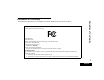
Declaration of Conformity DECLARATION OF CONFORMITY Per FCC CFR 47 Part 2 Section 2.1077(a) Responsible Party Name: Motorola, Inc. Address: 1301 East Algonquin Road, Schaumburg, IL 60196-1078, U.S.A. Phone Number: 1-800-927-2744 Declaration of Conformity This declaration is applicable to your radio only if your radio is labeled with the FCC logo shown below. Hereby declares that the product: Model Name: APX 7000 conforms to the following regulations: FCC Part 15, subpart B, section 15.107(a), 15.
Note: This equipment has been tested and found to comply with the limits for a Class B digital device, pursuant to part 15 of the FCC Rules. These limits are designed to provide reasonable protection against harmful interference in a residential installation. This equipment generates, uses and can radiate radio frequency energy and, if not installed and used in accordance with the instructions, may cause harmful interference to radio communications.
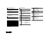
Contents Declaration of Conformity . . . . . . . . . . . . . . . . . .i Important Safety Information . . . . . . . . . . . . . vii Product Safety and RF Exposure Compliance . . . . . . . . . . . . . . . . . . . . . . . . . . . . . . vii Charging the Battery . . . . . . . . . . . . . . . . . . . . . . . . . 3 Battery Charger . . . . . . . . . . . . . . . . . . . . . . . . . . . . 3 Attaching the Battery . . . . . . . . . . . . . . . . . . . . . . . . . 3 Attaching the Antenna . . . . . . . . . . . . . . .
Intelligent Lighting Indicators . . . . . . . . . . . . . . . . . 13 Advanced Features . . . . . . . . . . . . . . . . . . . . . 23 Alert Tones . . . . . . . . . . . . . . . . . . . . . . . . . . . . . . . 14 Advanced Call Features . . . . . . . . . . . . . . . . . . . . . 23 Receiving and Responding to a Selective Call (ASTRO Conventional Only) . . . . . . . . . . . . . . . . . .23 Using the Dynamic Regrouping Feature (Trunking Only) . . . . . . . . . . . . . . . . . . . . . . . . . . . .
Secure Operations . . . . . . . . . . . . . . . . . . . . . . . . . 32 Selecting Secure Transmissions . . . . . . . . . . . . . . .32 Selecting Clear Transmissions . . . . . . . . . . . . . . . .32 Managing Encryption . . . . . . . . . . . . . . . . . . . . . . .33 Loading an Encryption Key . . . . . . . . . . . . . . . . . . 33 Using the Multikey Feature . . . . . . . . . . . . . . . . . . 33 Using the Key Zeroization Feature . . . . . . . . . . . . .
Cleaning Your Radio . . . . . . . . . . . . . . . . . . . . . . . 43 Handling Your Radio . . . . . . . . . . . . . . . . . . . . . . . 43 Servicing Your Radio . . . . . . . . . . . . . . . . . . . . . . . 44 Taking Care of the Battery . . . . . . . . . . . . . . . . . . . 44 Checking the Battery Charge Status . . . . . . . . . . . 44 Special Channel Assignments . . . . . . . . . . . . . . . . 49 Emergency Channel . . . . . . . . . . . . . . . . . . . . . . . .49 Non-Commercial Call Channel . . . . . . . .
Software Version Product Safety and RF Exposure Compliance All the features described in the following sections are supported by the radio's software version R01.00.00 or later. ! Before using this product, read the operating instructions for safe usage contained in the Product Safety and RF Exposure booklet enclosed with your radio. ATTENTION! This radio is restricted to occupational use only to satisfy FCC RF energy exposure requirements.
Computer Software Copyrights Computer Software Copyrights Documentation Copyrights The Motorola products described in this manual may include copyrighted Motorola computer programs stored in semiconductor memories or other media. Laws in the United States and other countries preserve for Motorola certain exclusive rights for copyrighted computer programs, including, but not limited to, the exclusive right to copy or reproduce in any form the copyrighted computer program.
Getting Started How to Use This Guide . . . . . . . . . . . . . . . . . . . . . . . . . page 1 Notations Used in This Manual . . . . . . . . . . . . . . . . . . . page 1 What Your Dealer/System Administrator Can Tell You. . . . . . . . . . . . . . . . . . . . . . . . . . . . . . . . page 2 Throughout the text in this publication, you will notice the use of WARNING, Caution, and Note. These notations are used to emphasize that safety hazards exist, and the care that must be taken or observed.
What Your Dealer/System Administrator Can Tell You Preparing Your Radio for Use Assemble your radio by following these steps: Preparing Your Radio for Use Check with your dealer or system administrator, if the radio is to be operated in extremely cold temperatures (less than -20°C), for the correct radio settings to ensure proper top display operation.
Charging the Battery ! • DO NOT replace the battery in any area labeled “hazardous atmosphere”. • DO NOT discard batteries in a fire. The Motorola-approved battery shipped with your radio is uncharged. Prior to using a new battery, charge it for a minimum of 16 hours to ensure optimum capacity and performance. For a list of Motorola-authorized batteries available for use with your radio, see Batteries and Battery Accessories on page 46.
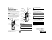
Preparing Your Radio for Use To remove the battery, turn the radio off. Squeeze the release latches on the bottom of the battery until the battery releases from the radio. Remove the battery from the radio. Battery Latch 4 English Attaching the Antenna With the radio turned off, set the antenna in its receptacle and turn clockwise to attach it to the radio.
Attaching the Accessory Connector Cover Note: To prevent damage to the connector, shield it with the connector cover when not in use. Insert the hooked end of the cover into the slot above the connector. Press downward on the cover’s top to seat it in the slot. Once in place, rotate the thumbscrew clockwise by hand until tight. Align the grooves of the belt clip with those of the radio and press upward until you hear a click.
Turning On the Radio Preparing Your Radio for Use Rotate the On/Off/Volume Control Knob clockwise until you hear a click. To turn off the radio, rotate the On/Off/Volume Control Knob counterclockwise until you hear a click. If the power-up test is successful, you see SELFTEST on the radio’s display momentarily, followed by the Home screen. Note: 6 English If the power-up test is unsuccessful, you see ERROR XX/YY (XX/YY is an alphanumeric code).
Adjusting the Volume Identifying Radio Controls Take a moment to review the following: Radio Parts and Controls . . . . . . . . . . . . . . . . . . . . . . . . page 8 Programmable Features . . . . . . . . . . . . . . . . . . . . . . . . page 9 Assignable Radio Functions . . . . . . . . . . . . . . . . . . . . page 9 Assignable Settings or Utility Functions . . . . . . . . . . page 10 Accessing the Preprogrammed Functions . . . . . . . . . . page 10 Push-To-Talk (PTT) Button. . . . . . . . . . . . . . . . .
Radio Parts and Controls 16-Position 10 Select Knob* 1 Antenna On/Off/Volume 5 Control Knob 2 LED Identifying Radio Controls 6 Top (Orange) 11 Button* 7 4 15 Display Top Side (Select) 3 Button* Accessory Connector Top 3-Position A/B/C Switch* 16 Microphone 2-Position Concentric Switch* Push-to-Talk 12 (PTT) Button Main 17 Speaker 8 Belt Clip 13 Side Button 1* 18 Battery 14 Side Button 2* 9 Battery Latch 8 English * These radio controls/buttons are programmable.
Programmable Features Your dealer can program the programmable buttons as shortcuts to radio functions or preset channels/groups depending on the duration of a button press: • Press – Pressing and releasing rapidly. • Long press – Pressing and holding for the preprogrammed duration (between 0.25 seconds and 3.75 seconds). • Hold down – Keeping the button pressed.
Zone Select – Allows selection from a list of zones. Push-To-Talk (PTT) Button Zone Bank – Allows selection from a larger list of zones. Assignable Settings or Utility Functions Flip – Flips the content of the top display. Light – Toggles display backlight on or off. Identifying Radio Controls TX Power Level – Toggles transmit power level between high and low. Voice Mute – Toggles voice mute on or off. Volume Set – Sets the volume set tone.
Identifying Status Indicators Status Icons . . . . . . . . . . . . . . . . . . . . . . . . . . . . . . . . . page 11 LED Indicator. . . . . . . . . . . . . . . . . . . . . . . . . . . . . . . . page 12 Intelligent Lighting Indicators . . . . . . . . . . . . . . . . . . . . page 13 Alert Tones . . . . . . . . . . . . . . . . . . . . . . . . . . . . . . . . . page 14 Status Icons The 112 x 32 pixel top monochrome display screen of your radio shows the radio status and operating conditions.
I Top Display Vote Scan Enabled The vote scan feature is enabled. View/Program Mode Radio is in the view or program mode. • On steady = View mode Identifying Status Indicators • Blinking = Program mode Zone Bank 1 A B •• C • or or A = Radio is in Zone 1. B = Radio is in Zone 2. C = Radio is in Zone 3. Zone Bank 2 D E• F • or or G 12 English • D = Radio is in Zone 4. E = Radio is in Zone 5. F = Radio is in Zone 6. Secure Operation • On = Secure operation. • Off = Clear operation.
Intelligent Lighting Indicators Note: This feature must be preprogrammed by a qualified radio technician. Backlight Notification Orange Emergency Alerts When The radio initiates an emergency alarm or call. The radio receives an emergency alarm or call. The radio battery is low. Red Critical Alerts The radio is out of range. The radio enters failsoft mode. The radio is unable to establish a full connection with the system. The radio receives a private call.
Alert Tones An alert tone is a sound or group of sounds. Your radio uses alert tones to inform you of your radio’s conditions. The following table lists these tones and when they occur. Identifying Status Indicators You Hear 14 English Short, Low-Pitched Tone Tone Name Radio Self Test Fail When radio fails its power-up self test. Reject When unauthorized request is made.
You Hear Tone Name Radio Self Test Pass Short, Medium-Pitched Tone Clear Voice Priority Channel Received Emergency Alarm Entry Central Echo Long, Medium-Pitched Tone Volume Set Emergency Exit Failsoft Automatic Call Back Talk Permit A Group of Medium-Pitched Tones Keyfail Console Acknowledge Received Individual Call When correct key is pressed. When radio passes its power-up self test. At beginning of a non-coded communication. When activity on a priority channel is received.
You Hear Tone Name Short, High-Pitched Tone (Chirp) Low-Battery Chirp Fast Ringing Identifying Status Indicators Ringing Heard When battery is below preset threshold value. When system is searching for target of Private Call. Enhanced Call Sent When waiting for target of Private Call to answer the call. Phone Call Received When a land-to-mobile phone call is received. Gurgle Dynamic Regrouping (When the PTT button is pressed) a dynamic ID has been received.
General Radio Operation General Radio Operation Once you understand how your APX 7000 Portable is configured, you are ready to use your radio. Selecting a Zone A zone is a group of channels. Use this navigation guide to familiarize yourself with the basic Call features: 3-Position A/B/C Switch Selecting a Zone . . . . . . . . . . . . . . . . . . . . . . . . . . . . . page 17 Selecting a Radio Channel . . . . . . . . . . . . . . . . . . . . . page 18 Receiving and Responding to a Radio Call . . . . . .
Selecting a Radio Channel A channel is a group of radio characteristics, such as transmit/ receive frequency pairs. Receiving and Responding to a Radio Call Once you have selected the required channel and/or zone, you can proceed to receive and respond to calls. General Radio Operation LED Indicator Use the following procedure to select a channel. Note: Your radio must be preprogrammed to allow you to use this feature.
Receiving and Responding to a Talkgroup Call Procedure: When you receive a talkgroup call (while on the Home screen), depending on how your radio is preprogrammed: 1 ASTRO Conventional Only: The LED lights up solid yellow. OR Trunking Only: The display shows the caller alias or ID. 2 Hold the radio vertically 1 to 2 inches (2.5 to 5.0 cm) from your mouth. 3 Press the PTT button to respond to the call. The LED lights up solid red. 4 Release the PTT button to listen.
2 Press the Call Response button within 20 seconds after the call indicators begin. 3 Press and hold the PTT button to talk. Release the PTT button to listen. 4 Press the Call Response button to hang up and return to the Home screen. Procedure: When you receive a Telephone Call: 1 You hear a telephone-type ringing and the LED blinks green. The backlight of the screen turns green and the display shows PHN CALL. 2 Press the Call Response button within 20 seconds after the call indicators begin.
Making a Radio Call • The preprogrammed Zone switch • The Channel Selector Knob Making a Talkgroup Call To make a call to a group of users, your radio must be configured as part of that talkgroup. Procedure: 1 Turn the Channel Selector Knob to select the channel with the desired talkgroup. 2 Hold the radio vertically 1 to 2 inches (2.5 to 5.0 cm) from your mouth. 3 Press the PTT button to make the call.
Monitoring Features General Radio Operation Radio users who switch from analog to digital radios often assume that the lack of static on a digital channel is an indication that the radio is not working properly. This is not the case. Digital technology quiets the transmission by removing the “noise” from the signal and allowing only the clear voice or data information to be heard. 22 Conventional Mode Operation Your radio may be preprogrammed to receive Private-Line® (PL) calls.
Advanced Features Receiving and Responding to a Selective Call (ASTRO Conventional Only) This feature allows you to receive a call from or to call a specific individual. It is intended to provide privacy and to eliminate the annoyance of having to listen to conversations that are of no interest to you. Procedure: 1 When you receive a Selective Call, you hear two alert tones and the LED lights up solid yellow. The backlight of the screen momentarily turns green and the display briefly shows CALL RCV.
Using the Dynamic Regrouping Feature (Trunking Only) This feature allows the dispatcher to temporarily reassign selected radios to a single special channel so they can communicate with each other. This feature is typically used during special operations and is enabled by a qualified radio technician. You will not notice whether your radio has this feature enabled until a dynamic regrouping command is sent by the dispatcher.
Classifying Regrouped Radios • Select-enabled radios are free to change to any available channel, including the dynamic-regrouping channel, once the user has selected the dynamic-regrouping position. • Select-disabled radios cannot change channels while dynamically regrouped. The dispatcher has forced the radio to remain on the dynamic-regrouping channel. The Scan or Private Call feature cannot be selected while your radio is Select Disabled.
2 A Scan icon indicates that the current channel is in the scan Advanced Features list as a non-priority channel. The LED lights up solid green. OR A Priority-Two Channel Scan icon indicates that the current channel is in the scan list as the Priority-Two channel. The LED blinks green. OR A Priority-One Channel Scan icon indicates that the current channel is in the scan list as the Priority-One channel. The LED rapidly blinks green.
Making a Dynamic Priority Change (Conventional Note: Scan Only) This change remains in effect until scan is turned off. Scan then reverts to the preprogrammed (original) setting. Procedure: 1 When the radio is locked onto the channel to be deleted, press the preprogrammed Nuisance Delete button. 2 The radio continues scanning the remaining channels in the list.
Call Alert Paging This feature allows your radio to work like a pager. The Emergency feature is used to indicate a critical situation. Note: If the Top (Orange) button is preprogrammed to send an emergency signal, this signal overrides any other communication over the selected channel. This feature must be preprogrammed by a qualified radio technician. Receiving a Call Alert Page Procedure: 1 When you receive a Call Alert page, you hear four repeating alert tones and the LED blinks green.
Sending an Emergency Call (Trunking Only) This feature allows you to send a data transmission, which identifies the radio sending the emergency, to the dispatcher. This feature gives your radio priority access on a channel. Procedure: 1 Press the preprogrammed Emergency button. 2 The display shows EMERGNCY and the current zone or channel. A short, medium-pitched tone sounds and the LED rapidly blinks red. OR An invalid tone sounds, if the selected channel does not support emergency.
3 Hold the radio vertically 1 to 2 inches (2.5 to 5.0 cm) from your mouth. 4 Press and hold the PTT button. Speak clearly into the microphone. 5 Release the PTT button to end the transmission and wait for a response from the dispatcher. 6 Press and hold the preprogrammed Emergency button for about a second to exit the Emergency Call mode. 3 The radio enters the Emergency Call state when: You receive the dispatcher’s acknowledgment. The display shows ACK RCVD.
Using the Emergency Keep-Alive Feature This feature allows you to send an Emergency Alarm to another radio without any audio or visual indicators. This feature, when enabled, prevents the radio from being turned off via the On/Off Control knob when the radio is in the Emergency state. Procedure: 1 Press the preprogrammed Emergency button. Note: The radio only exits the Emergency state using one of the ways mentioned in the previous sections.
Advanced Secure Operations Secure radio operation provides the highest commercially available level of voice security on both trunked and conventional channels. Unlike other forms of security, Motorola digital encryption provides signaling that makes it virtually impossible for others to decode any part of an encrypted message. Selecting Secure Transmissions Advanced Features Procedure: Turn the preprogrammed Secure/Clear switch to the secure position.
Using the Multikey Feature Loading an Encryption Key This feature allows the radio to be equipped with as many as 48 different encryption keys and supports the DES-OFB algorithm. Note: There are two types: Refer to the key-variable loader (KVL) manual for equipment connections and setup. Procedure: 1 Attach the KVL to your radio. 2 The display shows KEYLOAD, and all other radio functions, except for power down, backlight, and volume, are locked out.
Using the Key Zeroization Feature This feature allows you to erase all or selected encryption keys. Procedure: Use the preprogrammed Top Side (Select) button and Top (Orange) button to erase the single key in radios with the single-key option, and to erase all keys in radios with the multikey option. 1 Press and hold the Top Side (Select) button. 2 While holding Top Side (Select) button down, press the Top (Orange) button.
Trunking System Controls The failsoft system ensures continuous radio communications during a trunked system failure. If a trunking system fails completely, the radio goes into failsoft operation and automatically switches to its failsoft channel. Procedure: 1 During failsoft operation, your radio transmits and receives in conventional operation on a predetermined frequency. 2 A medium-pitched tone sounds every 10 seconds and the display shows FAILSOFT.
Using the Site Trunking Feature Viewing and Changing a Site If the zone controller loses communication with any site, that site reverts to site trunking. This feature allows you to view the number of the current site or force your radio to change to a new one. The display shows the currently selected zone/channel combination and STE TRNK. Viewing the Current Site Note: When this occurs, you can communicate only with other radios within your trunking site.
Utilities Procedure: Using the Flip Display This feature allows you to flip the content of the top display upside down. It is particularly useful when you would like to read the top display while the radio is still in the carry holder attached to your belt. Procedure: Press and hold the preprogrammed Light button to flip the display. position between Bank 1 and Bank 2. 2 The top display shows the status icons (A, B, C, D, E or F) or the zone name based on the bank and switch position selected.
Procedure: Turning Voice Mute On or Off 1 Press the preprogrammed Transmit Power Level Switch You can enable and disable voice transmission, if needed. to toggle the power level between low and high power. 2 The display shows LOW PWR and the low power icon. OR The display shows HIGH PWR and the high power icon. Procedure: 1 Press the preprogrammed Voice Mute button to turn the feature off or on.
Note: You will hear a brief, low-pitched, warning tone four seconds before the transmission times out. Procedure: 1 Hold down the PTT button longer than the preprogrammed time. You hear a short, low-pitched warning tone, the transmission is cut-off, and the LED goes out until you release the PTT button. 2 Release the PTT button. The timer resets. 3 Press the PTT button to re-transmit.
Digital Options Using the PL Defeat Feature One or more of the following options may be preprogrammed in your radio. Check with your dealer or system administrator for more information. This feature allows you to override any coded squelch (DPL or PL) that might be preprogrammed to a channel. The radio will also unmute to any digital activity on a digital channel. Option Advanced Features Digital Carrier-Operated Squelch (COS) 40 English Result You hear any digital traffic.
Using the Digital PTT ID Feature Your radio’s ID number is also automatically sent every time the PTT button is pressed. This is a per-channel feature. For digital voice transmissions, your radio’s ID is sent continuously during the voice message. Using the Smart PTT Feature (Conventional Only) Smart PTT is a per-personality, programmable feature used in conventional radio systems to keep radio users from talking over other radio conversations.
Caring for Your Radio Helpful Tips Take a moment to review the following: Caring for Your Radio . . . . . . . . . . . . . . . . . . . . . . . . . Cleaning Your Radio . . . . . . . . . . . . . . . . . . . . . . . . Handling Your Radio . . . . . . . . . . . . . . . . . . . . . . . . Servicing Your Radio . . . . . . . . . . . . . . . . . . . . . . . . Taking Care of the Battery. . . . . . . . . . . . . . . . . . . . . . Checking the Battery Charge Status . . . . . . . . . . . . Battery Recycling and Disposal.
Elastomer technology materials used for seals in rugged portable radios can age with time and environmental exposure. Therefore, Motorola recommends that rugged radios be checked annually as a preventive measure in order to assure the watertight integrity of the radio. Motorola details the disassembly, test, and reassembly procedures along with necessary test equipment needed to inspect, maintain and troubleshoot radio seals in the radio’s service manual.
• Avoid subjecting the radio to corrosives, solvents or spirits. Taking Care of the Battery • Do not disassemble the radio. • Keep the accessory-connector cover in place until ready to use the connector. Replace the cover immediately once the accessory has been disconnected. Helpful Tips Servicing Your Radio Proper repair and maintenance procedures will assure efficient operation and long life for this product.
Battery Recycling and Disposal U 76% to 100% full In the U.S. and Canada, Motorola participates in the nationwide Rechargeable Battery Recycling Corporation (RBRC) program for NiCd battery collection and recycling. Many retailers and dealers participate in this program. T 51% to 75% S 26% to 50% R 11% to 25% Q 10% or less (at 10%, the gauge begins blinking) For the location of the drop-off facility closest to you, access RBRC's Internet web site at www.rbrc.com or call 1-800-8BATTERY.
Accessories Your radio is compatible with the approved accessories listed in this chapter. Contact your dealer for details. Antennas . . . . . . . . . . . . . . . . . . . . . . . . . . . . . . . . . . . page 46 Batteries and Battery Accessories . . . . . . . . . . . . . . . page 46 Carry Accessories . . . . . . . . . . . . . . . . . . . . . . . . . . . . page 46 Belt Clips . . . . . . . . . . . . . . . . . . . . . . . . . . . . . . . . . page 46 Belt Loops . . . . . . . . . . . . . . . . . . . . . . . . . .
• Hard Leather Carry Case (High Activity) with 2.75” Swivel • Nylon Carry Case with 3” Fixed Belt Loop and T-Strap, for Long Radio (PMLN5328_) • Hard Leather Carry Case with 3” Fixed Belt Loop, D-Rings, and T-Strap, for Long Radio (PMLN5329_) • Hard Leather Carry Case (High Activity) with 2.
Audio Accessories • Small Remote Speaker Microphone, IP54, 3.5 mm Jack, Receive Only (PMMN4024_) • Small Remote Speaker Microphone, IP54, 3.5 mm Jack (PMMN4025_) • Noise Canceling Remote Speaker Microphone, IP54, 3.5 mm Jack (PMMN4062_) • Public Safety Microphone, 18 inch, IP55, 3.5 mm Jack (PMMN4059_) • Public Safety Microphone, 24 inch, IP55, 3.5 mm Jack (PMMN4060_) • Public Safety Microphone, 30 inch, IP55, 3.
State the position of the vessel in distress, using any information that will help responders to locate you, e.g.: 5 • latitude and longitude • bearing (state whether you are using true or magnetic north) • distance to a well-known landmark • vessel course, speed or destination State the nature of the distress. 6 Specify what kind of assistance you need. 7 State the number of persons on board and the number needing medical attention, if any.
Appendix: Maritime Radio Use in the VHF Frequency Range Operating Frequency Requirements A radio designated for shipboard use must comply with Federal Communications Commission Rule Part 80 as follows: • on ships subject to Part II of Title III of the Communications Act, the radio must be capable of operating on the 156.
Table A-1: VHF Marine Channel List (Continued) Table A-1: VHF Marine Channel List (Continued) Frequency (MHz) Transmit * 157.150 24 157.200 161.800 25 157.250 161.850 26 157.300 161.900 27 157.350 28 157.400 60 Frequency (MHz) Receive Channel Number Transmit Receive 161.750 75 *** *** 76 *** *** 77** 156.875 – 78 156.925 161.525 161.950 79 156.975 161.575 162.000 80 157.025 161.625 156.025 160.625 * 157.075 161.675 * 156.075 160.675 * 157.125 161.