6875952M01-D_TopD.
6875952M01-D_TopD.
6875952M01-D_TopD.book Page 3 Wednesday, May 12, 2010 11:35 AM m ASTRO® APX™ 7000 Series Digital Portable Radios Quick Reference Card Product Safety and RF Exposure Compliance Before using this product, read the operating instructions for safe usage contained in the Product Safety and RF C a u t i o n Exposure booklet enclosed with your radio. ! ATTENTION! This radio is restricted to occupational use only to satisfy FCC RF energy exposure requirements.
6875952M01-D_TopD.book Page 4 Wednesday, May 12, 2010 11:35 AM Sending an Emergency Call 1 Press the Emergency button. 2 Press and hold the PTT button. Speak clearly into the microphone. 3 Release the PTT button to end call. 4 Press and hold Emergency button to exit emergency. To exit emergency at any time, press and hold the Emergency button. Sending a Silent Emergency Call 1 Press the Emergency button. 2 The display does not change; the LED does not light up, and there is no tone.
6875952M01-D_TopD.book Page i Wednesday, May 12, 2010 11:35 AM Declaration of Conformity DECLARATION OF CONFORMITY Per FCC CFR 47 Part 2 Section 2.1077(a) Responsible Party Name: Motorola, Inc. Address: 1301 East Algonquin Road, Schaumburg, IL 60196-1078, U.S.A. Phone Number: 1-800-927-2744 Declaration of Conformity This declaration is applicable to your radio only if your radio is labeled with the FCC logo shown below.
875952M01-D_TopD.book Page ii Wednesday, May 12, 2010 11:35 AM Note: This equipment has been tested and found to comply with the limits for a Class B digital device, pursuant to part 15 of the FCC Rules. These limits are designed to provide reasonable protection against harmful interference in a residential installation.
6875952M01-D_TopD.book Page iii Wednesday, May 12, 2010 11:35 AM Contents Declaration of Conformity . . . . . . . . . . . . . . . . . .i Charging the Battery . . . . . . . . . . . . . . . . . . . . . . . . . 3 Battery Charger . . . . . . . . . . . . . . . . . . . . . . . . . . . . 3 Attaching the Battery . . . . . . . . . . . . . . . . . . . . . . . . . 3 Attaching the Antenna . . . . . . . . . . . . . . . . . . . . . . . . 4 Attaching the Accessory Connector Cover . . . . . . . .
6875952M01-D_TopD.book Page iv Wednesday, May 12, 2010 11:35 AM Alert Tones . . . . . . . . . . . . . . . . . . . . . . . . . . . . . . . 14 Classifying Regrouped Radios . . . . . . . . . . . . . . . .25 General Radio Operation . . . . . . . . . . . . . . . . .17 Scan Lists . . . . . . . . . . . . . . . . . . . . . . . . . . . . . . . . 25 Viewing a Scan List . . . . . . . . . . . . . . . . . . . . . . . . .25 Viewing and Changing the Priority Status . . . . . . . .25 Selecting a Zone . . . . . . . . .
6875952M01-D_TopD.book Page v Wednesday, May 12, 2010 11:35 AM Trunking System Controls . . . . . . . . . . . . . . . . . . . . 35 Using the Failsoft System . . . . . . . . . . . . . . . . . . . .35 Going Out of Range . . . . . . . . . . . . . . . . . . . . . . . .35 Using the Site Trunking Feature . . . . . . . . . . . . . . .36 Locking and Unlocking a Site . . . . . . . . . . . . . . . . .36 Viewing and Changing a Site . . . . . . . . . . . . . . . . .36 Viewing the Current Site . . . . . . . . . . . . .
6875952M01-D_TopD.book Page vi Wednesday, May 12, 2010 11:35 AM Glossary . . . . . . . . . . . . . . . . . . . . . . . . . . . . . .52 Commercial Warranty . . . . . . . . . . . . . . . . . . . .56 Contents Notes . . . . . . . . . . . . . . . . . . . . . . . . . . . . . . . . .
6875952M01-D_TopD.book Page vii Wednesday, May 12, 2010 11:35 AM Software Version Product Safety and RF Exposure Compliance All the features described in the following sections are supported by the radio's software version R02.00.00 or later. ! Caution Before using this product, read the operating instructions for safe usage contained in the Product Safety and RF Exposure booklet enclosed with your radio.
Computer Software Copyrights 6875952M01-D_TopD.book Page viii Wednesday, May 12, 2010 11:35 AM Computer Software Copyrights Documentation Copyrights The Motorola products described in this manual may include copyrighted Motorola computer programs stored in semiconductor memories or other media.
6875952M01-D_TopD.book Page 1 Wednesday, May 12, 2010 11:35 AM Getting Started How to Use This Guide . . . . . . . . . . . . . . . . . . . . . . . . . page 1 Notations Used in This Manual . . . . . . . . . . . . . . . . . . . page 1 What Your Dealer/System Administrator Can Tell You. . . . . . . . . . . . . . . . . . . . . . . . . . . . . . . . page 2 How to Use This Guide Throughout the text in this publication, you will notice the use of WARNING, Caution, and Note.
6875952M01-D_TopD.book Page 2 Wednesday, May 12, 2010 11:35 AM What Your Dealer/System Administrator Can Tell You Preparing Your Radio for Use Assemble your radio by following these steps: Preparing Your Radio for Use Check with your dealer or system administrator, if the radio is to be operated in extremely cold temperatures (less than -20°C), for the correct radio settings to ensure proper top display operation.
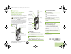
6875952M01-D_TopD.book Page 3 Wednesday, May 12, 2010 11:35 AM Charging the Battery ! WARNING • DO NOT replace the battery in any area labeled “hazardous atmosphere”. • DO NOT discard batteries in a fire. The Motorola-approved battery shipped with your radio is uncharged. Prior to using a new battery, charge it for a minimum of 16 hours to ensure optimum capacity and performance. For a list of Motorola-authorized batteries available for use with your radio, see Accessories on page 48.
6875952M01-D_TopD.book Page 4 Wednesday, May 12, 2010 11:35 AM Preparing Your Radio for Use To remove the battery, turn the radio off. Squeeze the release latches on the bottom of the battery until the battery releases from the radio. Remove the battery from the radio. Battery Latch 4 English Attaching the Antenna With the radio turned off, set the antenna in its receptacle and turn clockwise to attach it to the radio.
6875952M01-D_TopD.book Page 5 Wednesday, May 12, 2010 11:35 AM Attaching the Accessory Connector Cover Note: To prevent damage to the connector, shield it with the connector cover when not in use. Insert the hooked end of the cover into the slot above the connector. Press downward on the cover’s top to seat it in the slot. Once in place, rotate the thumbscrew clockwise by hand until tight. Align the grooves of the belt clip with those of the radio and press upward until you hear a click.
6875952M01-D_TopD.book Page 6 Wednesday, May 12, 2010 11:35 AM Turning On the Radio Preparing Your Radio for Use Rotate the On/Off/Volume Control Knob clockwise until you hear a click. To turn off the radio, rotate the On/Off/Volume Control Knob counterclockwise until you hear a click. If the power-up test is successful, you see SELFTEST on the radio’s display momentarily, followed by the Home screen.
6875952M01-D_TopD.book Page 7 Wednesday, May 12, 2010 11:35 AM Adjusting the Volume Identifying Radio Controls Take a moment to review the following: Radio Parts and Controls . . . . . . . . . . . . . . . . . . . . . . . . page 8 Programmable Features . . . . . . . . . . . . . . . . . . . . . . . . page 9 Assignable Radio Functions . . . . . . . . . . . . . . . . . . . . page 9 Assignable Settings or Utility Functions . . . . . . . . . . page 10 Accessing the Preprogrammed Functions . . . . . . . . . .
6875952M01-D_TopD.
6875952M01-D_TopD.book Page 9 Wednesday, May 12, 2010 11:35 AM Programmable Features Your dealer can program the programmable buttons as shortcuts to radio functions or preset channels/groups depending on the duration of a button press: • Press – Pressing and releasing rapidly. • Long press – Pressing and holding for the preprogrammed duration (between 0.25 seconds and 3.75 seconds). • Hold down – Keeping the button pressed.
6875952M01-D_TopD.book Page 10 Wednesday, May 12, 2010 11:35 AM Scan – Toggles scan on or off. Accessing the Preprogrammed Functions Scan List Programming – Selects the scan list for editing. Secure/Clear – Toggles secure operation on or off. You can access various radio functions through a short or long press of the relevant programmable buttons. Site Display – Displays the current site ID and RSSI value. Site Lock/Unlock – Locks onto a specific site.
6875952M01-D_TopD.book Page 11 Wednesday, May 12, 2010 11:35 AM Identifying Status Indicators Status Icons . . . . . . . . . . . . . . . . . . . . . . . . . . . . . . . . . page 11 LED Indicator. . . . . . . . . . . . . . . . . . . . . . . . . . . . . . . . page 12 Intelligent Lighting Indicators . . . . . . . . . . . . . . . . . . . . page 13 Alert Tones . . . . . . . . . . . . . . . . . . . . . . . . . . . . . . . . .
6875952M01-D_TopD.book Page 12 Wednesday, May 12, 2010 11:35 AM I Top Display Vote Scan Enabled The vote scan feature is enabled. View/Program Mode Radio is in the view or program mode. • On steady = View mode Identifying Status Indicators • Blinking = Program mode Zone Bank 1 A B •• C • or or A = Radio is in Zone 1. B = Radio is in Zone 2. C = Radio is in Zone 3. Zone Bank 2 D E• F • or or G • D = Radio is in Zone 4. E = Radio is in Zone 5. F = Radio is in Zone 6.
6875952M01-D_TopD.book Page 13 Wednesday, May 12, 2010 11:35 AM Intelligent Lighting Indicators Note: This feature must be preprogrammed by a qualified radio technician. Backlight Notification Orange Emergency Alerts When The radio initiates an emergency alarm or call. The radio receives an emergency alarm or call. The radio battery is low. Red Critical Alerts The radio is out of range. The radio enters failsoft mode. The radio is unable to establish a full connection with the system.
6875952M01-D_TopD.book Page 14 Wednesday, May 12, 2010 11:35 AM Alert Tones An alert tone is a sound or group of sounds. Your radio uses alert tones to inform you of your radio’s conditions. The following table lists these tones and when they occur. Identifying Status Indicators You Hear 14 English Short, Low-Pitched Tone Tone Name Radio Self Test Fail When radio fails its power-up self test. Reject When unauthorized request is made.
6875952M01-D_TopD.book Page 15 Wednesday, May 12, 2010 11:35 AM You Hear Tone Name Radio Self Test Pass Short, Medium-Pitched Tone Clear Voice Priority Channel Received Emergency Alarm Entry Central Echo Long, Medium-Pitched Tone Volume Set Emergency Exit Failsoft Automatic Call Back Talk Permit A Group of Medium-Pitched Tones Keyfail Console Acknowledge Received Individual Call When correct key is pressed. When radio passes its power-up self test. At beginning of a non-coded communication.
6875952M01-D_TopD.book Page 16 Wednesday, May 12, 2010 11:35 AM You Hear Tone Name Short, High-Pitched Tone (Chirp) Low-Battery Chirp Fast Ringing Identifying Status Indicators Ringing Heard When battery is below preset threshold value. When system is searching for target of Private Call. Enhanced Call Sent When waiting for target of Private Call to answer the call. Phone Call Received When a land-to-mobile phone call is received.
6875952M01-D_TopD.book Page 17 Wednesday, May 12, 2010 11:35 AM General Radio Operation General Radio Operation Once you understand how your APX 7000 Portable is configured, you are ready to use your radio. Selecting a Zone A zone is a group of channels. Use this navigation guide to familiarize yourself with the basic Call features: 3-Position A/B/C Switch Selecting a Zone . . . . . . . . . . . . . . . . . . . . . . . . . . . . . page 17 Selecting a Radio Channel . . . . . . . . . . . . . . . . . . .
6875952M01-D_TopD.book Page 18 Wednesday, May 12, 2010 11:35 AM Selecting a Radio Channel A channel is a group of radio characteristics, such as transmit/ receive frequency pairs. Receiving and Responding to a Radio Call Once you have selected the required channel and/or zone, you can proceed to receive and respond to calls. General Radio Operation LED Indicator Use the following procedure to select a channel. Note: Your radio must be preprogrammed to allow you to use this feature.
6875952M01-D_TopD.book Page 19 Wednesday, May 12, 2010 11:35 AM Receiving and Responding to a Talkgroup Call Procedure: When you receive a talkgroup call (while on the Home screen), depending on how your radio is preprogrammed: 1 ASTRO Conventional Only: The LED lights up solid yellow. OR Trunking Only: The display shows the caller alias or ID. 2 Hold the radio vertically 1 to 2 inches (2.5 to 5.0 cm) from your mouth. 3 Press the PTT button to respond to the call. The LED lights up solid red.
6875952M01-D_TopD.book Page 20 Wednesday, May 12, 2010 11:35 AM 2 Press the Call Response button within 20 seconds after the call indicators begin. 3 Press and hold the PTT button to talk. Release the PTT button to listen. 4 Press the Call Response button to hang up and return to the Home screen. Procedure: When you receive a Telephone Call: 1 You hear a telephone-type ringing and the LED blinks green. The backlight of the screen turns green and the display shows PHN CALL.
6875952M01-D_TopD.book Page 21 Wednesday, May 12, 2010 11:35 AM Making a Radio Call • The preprogrammed Zone switch • The Channel Selector Knob Making a Talkgroup Call To make a call to a group of users, your radio must be configured as part of that talkgroup. Procedure: 1 Turn the Channel Selector Knob to select the channel with the desired talkgroup. 2 Hold the radio vertically 1 to 2 inches (2.5 to 5.0 cm) from your mouth. 3 Press the PTT button to make the call.
6875952M01-D_TopD.book Page 22 Wednesday, May 12, 2010 11:35 AM Monitoring Features General Radio Operation Radio users who switch from analog to digital radios often assume that the lack of static on a digital channel is an indication that the radio is not working properly. This is not the case. Digital technology quiets the transmission by removing the “noise” from the signal and allowing only the clear voice or data information to be heard.
6875952M01-D_TopD.book Page 23 Wednesday, May 12, 2010 11:35 AM Advanced Features Receiving and Responding to a Selective Call (ASTRO Conventional Only) This feature allows you to receive a call from or to call a specific individual. It is intended to provide privacy and to eliminate the annoyance of having to listen to conversations that are of no interest to you. Procedure: 1 When you receive a Selective Call, you hear two alert tones and the LED lights up solid yellow.
6875952M01-D_TopD.book Page 24 Wednesday, May 12, 2010 11:35 AM Using the Dynamic Regrouping Feature (Trunking Only) This feature allows the dispatcher to temporarily reassign selected radios to a single special channel so they can communicate with each other. This feature is typically used during special operations and is enabled by a qualified radio technician. You will not notice whether your radio has this feature enabled until a dynamic regrouping command is sent by the dispatcher.
6875952M01-D_TopD.book Page 25 Wednesday, May 12, 2010 11:35 AM Classifying Regrouped Radios • Select-enabled radios are free to change to any available channel, including the dynamic-regrouping channel, once the user has selected the dynamic-regrouping position. • Select-disabled radios cannot change channels while dynamically regrouped. The dispatcher has forced the radio to remain on the dynamic-regrouping channel.
6875952M01-D_TopD.book Page 26 Wednesday, May 12, 2010 11:35 AM 2 A Scan icon indicates that the current channel is in the scan Advanced Features list as a non-priority channel. The LED lights up solid green. OR A Priority-Two Channel Scan icon indicates that the current channel is in the scan list as the Priority-Two channel. The LED blinks green. OR A Priority-One Channel Scan icon indicates that the current channel is in the scan list as the Priority-One channel. The LED rapidly blinks green.
6875952M01-D_TopD.book Page 27 Wednesday, May 12, 2010 11:35 AM Making a Dynamic Priority Change (Conventional Note: Scan Only) This change remains in effect until scan is turned off. Scan then reverts to the preprogrammed (original) setting. Procedure: 1 When the radio is locked onto the channel to be deleted, press the preprogrammed Nuisance Delete button. 2 The radio continues scanning the remaining channels in the list.
6875952M01-D_TopD.book Page 28 Wednesday, May 12, 2010 11:35 AM Call Alert Paging This feature allows your radio to work like a pager. The Emergency feature is used to indicate a critical situation. Note: If the Top (Orange) button is preprogrammed to send an emergency signal, this signal overrides any other communication over the selected channel. This feature must be preprogrammed by a qualified radio technician.
6875952M01-D_TopD.book Page 29 Wednesday, May 12, 2010 11:35 AM Sending an Emergency Call (Trunking Only) This feature allows you to send a data transmission, which identifies the radio sending the emergency, to the dispatcher. This feature gives your radio priority access on a channel. Procedure: 1 Press the preprogrammed Emergency button. 2 The display shows EMERGNCY and the current zone or channel. A short, medium-pitched tone sounds and the LED rapidly blinks red.
6875952M01-D_TopD.book Page 30 Wednesday, May 12, 2010 11:35 AM 3 Hold the radio vertically 1 to 2 inches (2.5 to 5.0 cm) from your mouth. 4 Press and hold the PTT button. Speak clearly into the microphone. 5 Release the PTT button to end the transmission and wait for a response from the dispatcher. 6 Press and hold the preprogrammed Emergency button for about a second to exit the Emergency Call mode. 3 The radio enters the Emergency Call state when: You receive the dispatcher’s acknowledgment.
6875952M01-D_TopD.book Page 31 Wednesday, May 12, 2010 11:35 AM Using the Emergency Keep-Alive Feature This feature allows you to send an Emergency Alarm to another radio without any audio or visual indicators. This feature, when enabled, prevents the radio from being turned off via the On/Off Control knob when the radio is in the Emergency state. Procedure: 1 Press the preprogrammed Emergency button.
6875952M01-D_TopD.book Page 32 Wednesday, May 12, 2010 11:35 AM Advanced Secure Operations Secure radio operation provides the highest commercially available level of voice security on both trunked and conventional channels. Unlike other forms of security, Motorola digital encryption provides signaling that makes it virtually impossible for others to decode any part of an encrypted message.
6875952M01-D_TopD.book Page 33 Wednesday, May 12, 2010 11:35 AM Using the Multikey Feature Loading an Encryption Key This feature allows the radio to be equipped with as many as 48 different encryption keys and supports the DES-OFB algorithm. Note: There are two types: Refer to the key-variable loader (KVL) manual for equipment connections and setup. Procedure: 1 Attach the KVL to your radio.
6875952M01-D_TopD.book Page 34 Wednesday, May 12, 2010 11:35 AM Erasing the Selected Encryption Keys This feature allows you to erase all or selected encryption keys. Procedure: Use the preprogrammed Top Side (Select) button and Top (Orange) button to erase the single key in radios with the single-key option, and to erase all keys in radios with the multikey option. 1 Press and hold the Top Side (Select) button. 2 While holding Top Side (Select) button down, press the Top (Orange) button.
6875952M01-D_TopD.book Page 35 Wednesday, May 12, 2010 11:35 AM Trunking System Controls The failsoft system ensures continuous radio communications during a trunked system failure. If a trunking system fails completely, the radio goes into failsoft operation and automatically switches to its failsoft channel. Procedure: 1 During failsoft operation, your radio transmits and receives in conventional operation on a predetermined frequency.
6875952M01-D_TopD.book Page 36 Wednesday, May 12, 2010 11:35 AM Using the Site Trunking Feature Viewing and Changing a Site If the zone controller loses communication with any site, that site reverts to site trunking. This feature allows you to view the number of the current site or force your radio to change to a new one. The display shows the currently selected zone/channel combination and STE TRNK.
6875952M01-D_TopD.book Page 37 Wednesday, May 12, 2010 11:35 AM Utilities Procedure: Using the Flip Display This feature allows you to flip the content of the top display upside down. It is particularly useful when you would like to read the top display while the radio is still in the carry holder attached to your belt. Procedure: Press and hold the preprogrammed Light button to flip the display. position between Bank 1 and Bank 2.
6875952M01-D_TopD.book Page 38 Wednesday, May 12, 2010 11:35 AM Procedure: Turning Voice Mute On or Off 1 Press the preprogrammed Transmit Power Level Switch You can enable and disable voice transmission, if needed. to toggle the power level between low and high power. 2 The display shows LOW PWR and the low power icon. OR The display shows HIGH PWR and the high power icon. Procedure: 1 Press the preprogrammed Voice Mute button to turn the feature off or on.
6875952M01-D_TopD.book Page 39 Wednesday, May 12, 2010 11:35 AM Note: You will hear a brief, low-pitched, warning tone four seconds before the transmission times out. Procedure: 1 Hold down the PTT button longer than the preprogrammed time. You hear a short, low-pitched warning tone, the transmission is cut-off, and the LED goes out until you release the PTT button. 2 Release the PTT button. The timer resets. 3 Press the PTT button to re-transmit.
6875952M01-D_TopD.book Page 40 Wednesday, May 12, 2010 11:35 AM Digital Options Using the PL Defeat Feature One or more of the following options may be preprogrammed in your radio. Check with your dealer or system administrator for more information. This feature allows you to override any coded squelch (DPL or PL) that might be preprogrammed to a channel. The radio will also unmute to any digital activity on a digital channel.
6875952M01-D_TopD.book Page 41 Wednesday, May 12, 2010 11:35 AM Using the Digital PTT ID Feature Your radio’s ID number is also automatically sent every time the PTT button is pressed. This is a per-channel feature. For digital voice transmissions, your radio’s ID is sent continuously during the voice message.
6875952M01-D_TopD.book Page 42 Wednesday, May 12, 2010 11:35 AM Voice Announcement This feature enables the radio to audibly indicate the current feature mode, Zone or Channel the user has just assigned. This audio indicator can be customized per customer requirements. This is typically useful when the user is in a difficult condition to read the content shown on the display. Each voice announcement is within a limit of three seconds maximum.
6875952M01-D_TopD.book Page 43 Wednesday, May 12, 2010 11:35 AM • Change to a new channel remaining within the current zone. The radio announces the current channel. to launch or terminate Scan, PL Disabled, Talkaround/Direct or Transmit Inhibit. The radio announces the corresponding feature activation.
6875952M01-D_TopD.book Page 44 Wednesday, May 12, 2010 11:35 AM Caring for Your Radio Helpful Tips Take a moment to review the following: Caring for Your Radio . . . . . . . . . . . . . . . . . . . . . . . . . Cleaning Your Radio . . . . . . . . . . . . . . . . . . . . . . . . Handling Your Radio . . . . . . . . . . . . . . . . . . . . . . . . Servicing Your Radio . . . . . . . . . . . . . . . . . . . . . . . . Taking Care of the Battery. . . . . . . . . . . . . . . . . . . . . .
6875952M01-D_TopD.book Page 45 Wednesday, May 12, 2010 11:35 AM Caution Elastomer technology materials used for seals in rugged portable radios can age with time and environmental exposure. Therefore, Motorola recommends that rugged radios be checked annually as a preventive measure in order to assure the watertight integrity of the radio.
6875952M01-D_TopD.book Page 46 Wednesday, May 12, 2010 11:35 AM • Avoid subjecting the radio to corrosives, solvents or spirits. Taking Care of the Battery • Do not disassemble the radio. • Keep the accessory-connector cover in place until ready to use the connector. Replace the cover immediately once the accessory has been disconnected. Helpful Tips Servicing Your Radio Proper repair and maintenance procedures will assure efficient operation and long life for this product.
6875952M01-D_TopD.book Page 47 Wednesday, May 12, 2010 11:35 AM Battery Recycling and Disposal U 76% to 100% full In the U.S. and Canada, Motorola participates in the nationwide Rechargeable Battery Recycling Corporation (RBRC) program for NiCd battery collection and recycling. Many retailers and dealers participate in this program.
6875952M01-D_TopD.book Page 48 Wednesday, May 12, 2010 11:35 AM Accessories For a list of Motorola-approved antennas and other accessories, visit the following website: http://www.motorola.com/governmentandenterprise On the website, search for APX 7000 Multi-Band Portable Radio. You will see the accessories information besides the specifications of the radio. You can also contact your dealer for details. Contact your dealer for details. The certifications for the accessories are as below.
6875952M01-D_TopD.book Page 49 Wednesday, May 12, 2010 11:35 AM State the position of the vessel in distress, using any information that will help responders to locate you, e.g.: 5 • latitude and longitude • bearing (state whether you are using true or magnetic north) • distance to a well-known landmark • vessel course, speed or destination State the nature of the distress. 6 Specify what kind of assistance you need.
6875952M01-D_TopD.book Page 50 Wednesday, May 12, 2010 11:35 AM Appendix: Maritime Radio Use in the VHF Frequency Range Operating Frequency Requirements A radio designated for shipboard use must comply with Federal Communications Commission Rule Part 80 as follows: • on ships subject to Part II of Title III of the Communications Act, the radio must be capable of operating on the 156.
6875952M01-D_TopD.book Page 51 Wednesday, May 12, 2010 11:35 AM Table A-1: VHF Marine Channel List (Continued) Table A-1: VHF Marine Channel List (Continued) Frequency (MHz) Transmit * 157.150 24 157.200 161.800 25 157.250 161.850 26 157.300 161.900 27 157.350 28 157.400 60 Frequency (MHz) Receive Channel Number Transmit Receive 161.750 75 *** *** 76 *** *** 77** 156.875 – 78 156.925 161.525 161.950 79 156.975 161.575 162.000 80 157.025 161.625 156.025 160.
6875952M01-D_TopD.book Page 52 Wednesday, May 12, 2010 11:35 AM Term Glossary Carrier Squelch Feature that responds to the presence of an RF carrier by opening or unmuting (turning on) a receiver’s audio circuit. A squelch circuit silences the radio when no signal is being received so that the user does not have to listen to “noise.” Central Controller A software-controlled, computer-driven device that receives and generates data for the trunked radios assigned to it.
6875952M01-D_TopD.book Page 53 Wednesday, May 12, 2010 11:35 AM Term Displayed by the radio after three failed attempts to unlock the radio.The radio must be powered off and on prior to another attempt. Digital Private Line (DPL) A type of coded squelch using data bursts. Similar to PL except a digital code is used instead of a tone. Digital Signal An RF signal that has a pulsed, or discrete, nature, rather than a continuous nature. Dispatcher An individual who has radio system management duties.
6875952M01-D_TopD.book Page 54 Wednesday, May 12, 2010 11:35 AM Glossary Term Definition Non-Tactical/ Revert The user talks on a preprogrammed emergency channel. The emergency alarm is sent out on this same channel. OTAR Over-the-air rekeying. Page A one-way alert, with audio and/or display messages. Personality A set of unique features specific to a radio. Preprogrammed Refers to a software feature that has been activated by a qualified radio technician.
6875952M01-D_TopD.book Page 55 Wednesday, May 12, 2010 11:35 AM Term Definition An organization or group of radio users who communicate with each other using the same communication path. Trunking The automatic sharing of communications paths between a large number of users (see Conventional). Trunking Priority Monitor Scan List A scan list that includes talkgroups that are all from the same trunking system. USK Unique Shadow Key. Zone A grouping of channels.
75952M01-D_TopD.book Page 56 Wednesday, May 12, 2010 11:35 AM Product manufactured by MOTOROLA. MOTOROLA assumes no obligations or liability for additions or modifications to this warranty unless made in writing and signed by an officer of MOTOROLA. Commercial Warranty Limited Warranty MOTOROLA COMMUNICATION PRODUCTS Commercial Warranty I. WHAT THIS WARRANTY COVERS AND FOR HOW LONG: 56 MOTOROLA INC.
6875952M01-D_TopD.book Page 57 Wednesday, May 12, 2010 11:35 AM INABILITY TO USE SUCH PRODUCT, TO THE FULL EXTENT SUCH MAY BE DISCLAIMED BY LAW. SOME STATES DO NOT ALLOW THE EXCLUSION OR LIMITATION OF INCIDENTAL OR CONSEQUENTIAL DAMAGES OR LIMITATION ON HOW LONG AN IMPLIED WARRANTY LASTS, SO THE ABOVE LIMITATION OR EXCLUSIONS MAY NOT APPLY. This warranty gives specific legal rights, and there may be other rights which may vary from state to state. IV.
6875952M01-D_TopD.book Page 58 Wednesday, May 12, 2010 11:35 AM Commercial Warranty VI.