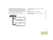
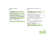
Note: Only two (2) control heads are supported in the one active mode. Transceiver Z1 ZONE CHAN PWR Follow the procedure below to change the command between the two control heads. Procedure: Press the Menu Select button directly below F/R. OR Press the Menu Select button preprogrammed user button on the keypad microphone. Advanced Features The Volume knob, DIM button, Front/Rear (F/R) softkey and Emergency button remain active on the inactive control head, while all other controls are disabled.
Contacts Note: This feature provides “address-book” capabilities on your radio. Each entry corresponds to an alias (name) or ID (number) that you use to initiate a call. If the feature inactivity timer is enabled, your radio automatically exits the feature when your radio is left idle long enough for the time to expire. You will hear the Menu Inactive Exit Tone upon feature exit. Contacts manages up to 2,500 contact entries, alphabetically sorted according to entry alias.
7 Hold the microphone vertically 1 to 2 inches (2.5 to 5.0 cm) from your mouth. display shows the subscriber alias. 9 Press and hold the PTT button to talk. The LED lights up solid red. OR Release the PTT button to listen. The LED lights up solid green. 10 If there is no voice activity for a programmed period of time, the call ends. OR The call ends when it reaches the maximum ring time. display shows the subscriber alias. 7 Press and hold the PTT button to talk. The LED lights up solid red.
Adding a New Contact Entry Procedure: 1 > or < to CNTS. 2 Press the Menu Select button directly below CNTS. The entries are alphabetically sorted. 3 > or < to {NEW CONTACT} and press the Menu Select button directly below SEL. 4 The display shows NAME. Press the Menu Select button directly below EDIT. Use the keypad to enter the name. Advanced Features Press < to move one space to the left. Press > to move one space to the right.
Adding a Contact to a Call List or Phone List Procedure: Procedure: 1 > or < to CNTS. 1 > or < to CNTS. 2 Press the Menu Select button directly below CNTS. The 2 Press the Menu Select button directly below CNTS. The entries are alphabetically sorted. 3 > or < to the entry you want to delete and press the Menu Select button directly below OPTN. 4 > or < to DELETE and press the Menu Select button directly below SEL. The display shows CONFIRM DEL?. 5 Select YES to delete the entry.
Editing a Contact in a Call List or a Phone List Editing an Entry Alias Procedure: 1 > or < to CNTS. 2 Press the Menu Select button directly below CNTS. The entries are alphabetically sorted. 3 > or < to the entry you want to edit and press the Menu Select button directly below OPTN. 4 > or < to EDIT and press the Menu Select button directly Advanced Features below SEL. 5 > or < to the entry alias you wish to change and press the Menu Select button directly below EDIT. 6 A cursor appears.
Press the Menu Select button directly below OK once you have finished. The display returns to the Edit Contact screen. 8 Press the Menu Select button directly below DONE to save your changes and return to the main screen for Contacts. Editing a Call Type Procedure: 1 > or < to CNTS. 2 Press the Menu Select button directly below CNTS. The entries are alphabetically sorted. 3 > or < to the entry you want to edit and press the Menu Select button directly below OPTN.
Scan Lists Scan lists are created and assigned to individual channels/ groups. Your radio scans for voice activity by cycling through the channel/group sequence specified in the scan list for the current channel/group. This feature lets you change scan list members and priorities. Note: The maximum number of members for a trunking priority monitor scan list is 50; for a conventional scan list, 30; and for a talkgroup scan list, 250. Your radio can support up to 200 different scan lists.
Use the Mode Knob to select additional channels to be added or deleted. Home screen. See Viewing and Changing the Priority Status on page 50 for more information on how to add and/or change the priority of the currently displayed channel in the scan list. Changing the Scan List Status Procedure: 1 Long press the preprogrammed Scan side button. 2 > or < to the member you want to edit. 5 Press H to exit scan list programming and return to the Home screen.
Viewing and Changing the Priority Status Procedure: 1 Below the SEL, DEL, and RCL screen, press the Menu Select button directly below SEL to view and/or change the priority status of the currently displayed channel. OR Below the SEL, DEL, and RCL screen, press the 3 button or press the Menu Select button directly below SEL, one or more times to view and/or change the scan list status icon of the currently displayed channel.
Turning Scan On While Disregarding the Squelch Code (Conventional Channels Only) 1 > or < to MON. 2 Press the Menu Select button directly below MON. 3 The brief MONITOR ON display indicates that the radio is disregarding the squelch code. While scanning for activity, you can still receive fleetwide, system-wide, dynamic regrouping, incoming telephone interconnect and Private Conversation/Call Alert calls. Respond to these types of calls as you would normally on the selected channel.
Deleting a Nuisance Channel Changing Priorities Status While Scan is On If a channel continually generates unwanted calls or noise (termed a “nuisance” channel), you can temporarily remove the unwanted channel from the scan list. While the radio is scanning, the dynamic priority change feature allows you to temporarily change any channel in a scan list (except for the Priority-One channel) to the Priority-Two channel.
Restoring Priorities in a Scan List To restore the original channel priorities in a scan list, do one of the following: • Turn scan off, then on. OR • Change channels. • OR Turn off the radio, and then turn it back on. Hang Up (HUB) To temporarily suspend Scan Mode operation, remove the control head from the Hang Up Box (HUB). You are allowed to use the control head while scan is suspended. However, Priority Member scanning is not suspended. This feature applies to all Scan Lists and Scan Types.
Receiving a Call Alert Page Sending a Call Alert Page Procedure: Note: When you receive a Call Alert page 1 You hear four repeating alert tone and the green LED blinks. OR You hear one alert tone and the green LED blinks if Call Alert Tone Auto Reset is enabled. 2 The call received icons blinks and the display shows PAGE RECEIVED. 3 Press the PTT button to answer. Advanced Features OR Press any button to clear the Call Alert page.
Press the Menu Select button directly below OK to return to the main screen for Contacts. Press the Menu Select button directly below OK to return to the main screen for Contacts. In-Call User Alert 1 > or < to CALL. You can enable and disable voice transmission, if needed. 2 Press the Menu Select button directly below CALL. 3 > or < to select the required ID, press the PTT button to initiate the call.
Emergency Operation The Emergency feature is used to indicate a critical situation. If the Orange button is preprogrammed to send an emergency signal, this signal overrides any other communication over the selected channel.
Procedure: Procedure: 1 Press the preprogrammed Emergency button to activate 1 Press preprogrammed Emergency button. 2 A tone sounds and the display alternates EMERGENCY and the home display. OR A short low-pitched tone sounds when the selected channel does not support emergency. 3 Hold the microphone vertically 1 to 2 inches (2.0 to 2.5 cm) from your mouth. 4 Press and hold the PTT button. Speak clearly into the microphone. the emergency call/alarm feature.
Sending a Silent Emergency Alarm Special Considerations for Emergencies This feature allows you to send an Emergency Alarm to another radio without any audio or visual indicator. • If you press the emergency button while in a channel that has Upon acknowledgement, your radio’s microphone is automatically activated, allowing you to communicate with the other radio without pressing the PTT button.
Advanced Features Automatic Registration Service (ARS) Data applications within the fixed network can determine the presence of a device on the system and send data to the device. For example: Text Messaging Service (TMS). The Automatic Registration Service for the radio consists of two (2) modes: • ARS Server Mode (default mode) • ARS Non Server Mode Note: The default ARS mode can be changed by a qualified radio technician using the radio’s programming software.
Accessing the User Login Feature Logging In as a User This feature allows you as the user to be associated with the radio. With this association, every data application (Example: Text Messaging Service) takes on a friendly username. Procedure: You can still send text messages without logging in as a user. The user login feature only enables the recipient of your message to identify you as the sender by assigning a username to your message.
The maximum PIN length is 4 digits. The PIN number will appear as asterisks. Logging Out Once the data application registration is completed, you can log out. 9 In ARS server mode, the display shows the User Login Procedure: Indicator icon, the ID, IN PPROGRESS and CNCL. OR In ARS non-server mode, the display shows the User Login Indicator icon, the ID, LOGGED IN and LOGT. In non-ARS enabled mode, the display shows OFFLINE and LOGT.
Text Messaging Service (TMS) This feature allows you to send and receive text messages. The maximum length of characters for a text message is 200. There are three (3) types of text messages: • A new text message (free form message) • A predefined message (quick text message) Note: If the feature inactivity timer is enabled, your radio automatically exits the feature when your radio is left idle long enough for the time to expire. You will hear the Menu Inactive Exit Tone upon feature exit.
Composing and Sending a New Text Message During the uppercase and lowercase mode, multitapping the keys only scrolls through the letters. For example, A->B->C, a->b->c. During the num lock mode, except for 1, pressing the keypad only enters the numeric digits. Subsequent presses of the same key inserts the same digit to the text message (no multi-tap). Procedure: 1 > or < to TMS. 2 Press the Menu Select button directly below TMS to access the TMS feature screen.
9 Press the Menu Select button below SEND to send the message. OR Press the PTT button to send the message. 10 The display shows the SEND MESSAGE screen and SENDING MSG. 11 If the message is sent, a tone sounds and the display shows MSG SENT. OR If the message is not sent, a low tone sounds and the display shows SEND FAILED. Advanced Features If the message fails to send, the radio returns you to the main TMS screen.
7 Press the Menu Select button directly below OPTN. 8 > or < to SEND and press the Menu Select button directly below SEL to send the message. 9 > or < to scroll through the address list and highlight the required address. OR > or < to {OTHER RECPNT} and press the Menu Select button below EDIT. A blinking cursor appears in the ENTER ADDRESS screen. Use the keypad to type the address entry. 10 Press the Menu Select button below SEND to send the message. OR Press the PTT button to send the message.
Using the Priority Status and Request Reply Features Before sending your message, you can append a priority message and/or a request reply to your message. Appending or Removing a Priority Status to a Text Message Advanced Features Note: The Priority Message icon on a message does not imply that the message gets higher priority over the other messages when it is being transmitted. It is just an indication that can be embedded into a message to let the receiver know that the message is important.
> or < to RQRP and press the Menu Select button directly Managing Text Messages below RQRP to request for a reply. normal message icon on the label bar. Removing a Priority Status and a Reply Request from a Text Message When an outgoing message is indicated with priority status and reply status icons, follow the procedure below to remove these indicators. Procedure: 1 Press the Menu Select button directly below OPTN.
Viewing a Text Message from the Inbox • Select RPLY to reply the message. The Inbox can hold up to thirty (30) messages. • Select DEL to delete the message. Advanced Features Note: 68 > or < to read the message if fills more than one • Select BACK to return to the previous screen. screen. Note: Procedure: Press the preprogrammed Data Feature button or the TMS Feature button to access the TMS feature screen, and proceed to Step 3.
Replying to a Received Text Message The original date and time stamp, address and message content is automatically appended to the reply message. Procedure: 1 > or < to the required aliases or ID and press the Menu Select button below SEL to view the message. 2 Press the Menu Select button directly below RPLY to reply to a message. 3 > or < to NEW and press the Menu Select button directly below NEW. OR > or < to LIST and press the Menu Select button directly below LIST for a predefined message.
Accessing the Drafts Folder Managing Sent Text Messages This folder stores the messages that were saved previously. The Drafts folder can hold up to 10 messages. The oldest draft in the folder is deleted when the 11th message comes in. Once a message is sent to another radio, it is saved in the Sent folder. The most recent sent text message is always added to the top of the Sent list. Procedure: The Sent folder is capable of storing a maximum of ten (10) last sent messages.
Press the Menu Select button directly below OPTN, DEL, or BACK to access the option. • Select DEL to delete the message. • Select BACK to return to the previous screen. Note: The icon at the top right corner of the screen indicates the status of the message. See Text Messaging Service (TMS) Icons on page 18 for more information. Sending a Sent Text Message Procedure: 1 Press the Menu Select button directly below OPTN while viewing the message.
Deleting Text Messages Procedure: From the Inbox, Draft, or Sent screen: 1 > or < to scroll through the messages. 2 Press the Menu Select button directly below DEL to view the delete options. 3 Press the Menu Select button directly below CURR to delete Advanced Features the current message. OR Press the Menu Select button directly below ALL to delete all the messages.
7 When the key has been loaded successfully, the radio sounds a short tone for single-key radios. Procedure: 1 Attach the KVL to your radio. 2 Press the Menu Select button below TARGET. 3 Press the Menu Select button below LOAD. 4 Press the Menu Select button below GROUP. 5 > or < to required group. 6 Press the Menu Select button below LOAD to load the key to your radio. 7 Your mobile radio display shows KEYLOADING when it is loading key(s) from KVL.
Selecting an Encryption Key (Conventional Only) Enabling Secure Transmission Procedure: Procedure: 1 > or < to KEY. 1 > or < to SEC and Press the Menu Select button directly 2 Press the Menu Select button directly below KEY. The display shows the last user-selected and stored encryption key, and the available menu selections. 3 > or < to scroll through the encryption keys. OR Use the keypad to enter the number of the desired key.
Selecting a Keyset 5 The radio exits keyset selection and returns to the Home This feature allows you to select one or more groups of several encryption keys from among the available keys stored in the radio. Erasing the Selected Encryption Keys screen. This feature allows you to erase all or selected encryption keys. Every channel to which one of the original keys was tied now has the equivalent new key instead. 2 Press the Menu Select button directly below ERAS.
Requesting an Over-the-Air Rekey This feature, also known as OTAR, allows the dispatcher to reprogram the encryption keys in the radio remotely. The dispatcher performs the rekey operation upon receiving a rekey request from the user. Procedure: 1 > or < to REKY. 2 Press the Menu Select button directly below REKY. Advanced Features 3 Press the PTT button to send the rekey request. OR Press the PTT button again, or the H or Emergency button, to exit the feature and transmit in normal mode.
Enhancing GPS Performance • Between tall buildings or under dense tree-cover Sometimes, the GPS feature may be unable to complete a location calculation successfully. You then see a message indicating that your radio cannot connect to enough visible satellites. • In temperature extremes outside the operating limits of your radio Even where location information can be calculated in such situations, it may take longer to do so, and your location estimate may not be as accurate.
The radio also stores four (4) preprogrammed waypoints. These coordinates cannot be deleted. Programmable Waypoints Preprogrammed Waypoints Fixed location coordinates: • Home User-configurable location coordinates. • Emergency • Last Known Location Advanced Features • Destination Only the alias is editable, not the coordinates. The Home and Destination coordinates are editable. Coordinates can be deleted one at a time, or all at once. Coordinates cannot be deleted.
8 Press the Menu Select button directly below EXIT to exit The radio also exits the menu if the emergency button is pressed. Saving a Waypoint Procedure: OR While in the current location display: Follow the procedure below to turn off the GPS (This feature is enabled by a qualified radio technician.): 1 Press the Menu Select button directly below OPTN. 1 > or < to LOC. 2 Press the Menu Select button directly below LOC. The display shows PREVIOUS LOC .
5 Press H or the PTT button (if preprogrammed) to exit this menu. Viewing a Saved Waypoint Advanced Features Procedure: Editing the Alias of a Waypoint Procedure: While in the current location display: 1 Press the Menu Select button directly below OPTN. While in the current location display: 2 > or < to WAYPOINTS. 1 Press the Menu Select button directly below OPTN. 3 Press the Menu Select button directly below SEL. 2 > or < to WAYPOINTS. 4 > or < to desired waypoints.
Press the Menu Select button directly below CNCL to return to the Waypoints main screen. 10 Press H or the PTT button (if preprogrammed) to exit this menu. Editing the Coordinates of a Waypoint Procedure: While in the current location display: 1 Press the Menu Select button directly below OPTN. 2 > or < to WAYPOINTS and press the Menu Select button directly below SEL. 3 > or < to desired waypoints. 4 Press the Menu Select button directly below OPTN.
Deleting a Single Saved Waypoint Deleting All Saved Waypoints Procedure: Procedure: While in the current location display: 1 Press the Menu Select button directly below OPTN. 1 Press the Menu Select button directly below OPTN. 2 > or < to WAYPOINTS and press the Menu Select button 2 > or < to WAYPOINTS. 3 Press the Menu Select button directly below SEL. 4 > or < to desired waypoints. Advanced Features 5 Press the Menu Select button directly below OPTN.
Measuring the Distance and Bearing from a Saved Waypoint 1 Press the Menu Select button directly below OPTN. 2 > or < to DIST FRM HERE and press the Menu Select button directly below SEL. 3 > or < to the required waypoint, and press the Menu Select button directly below SEL. 4 The display shows the distance and bearing from the current to the selected coordinates.
Trunking System Controls Using the Failsoft System The failsoft system ensures continuous radio communications during a trunked system failure. If a trunking system fails completely, the radio goes into failsoft operation and automatically switches to its failsoft channel. The failsoft condition is indicated by a faint beeping tone every nine seconds (radio unsquelched) until the trunking system returns to normal operation.
Locking and Unlocking a Site The SmartZone® feature extends communications beyond the reach of a single-trunked site (antenna location) when operating in a SmartZone system. SmartZone units provide expanded wide-area coverage. This feature allows your radio to lock onto a specific site and not roam among wide-area talkgroup sites. This feature should be used with caution, since it inhibits roaming to another site in a wide-area system.
Viewing and Changing a Site Changing the Current Site This feature allows you to view the number of the current site or force your radio to change to a new one. Procedure: Viewing the Current Site Procedure: 1 Press the preprogrammed Site Search button. OR > or < to RSSI. 2 The display momentarily shows the name of the current site Advanced Features and its corresponding received signal strength indicator (RSSI). 86 English 1 Press and hold down the preprogrammed Site Search button.
Initiating an Announcement The announcement capability allows you to make announcements to the entire user group, as well as monitor talkgroup calls and other announcements. If your radio has been programmed to allow announcement calls: Announcement calls are handled in two different ways, depending on the trunked central controller configuration. The two types are called ruthless and non-ruthless preemption.
Utilities Note: Viewing Recent Calls List This feature allows you to view the recent incoming and outgoing call information of the following call types: Selecting the Power Level • Call Alert You can select the power level at which your radio transmits. The radio always turns on to the default setting.
3 The display shows LOW POWER and the low power icon. Selecting a Radio Profile This feature allows you to manually switch the visual and audio settings of the radio. The display, backlight, alert tones, and audio settings are defined according to the preprogrammed radio settings of each radio profile. 4 Press the Menu Select button directly below SEL to select the required radio profile. OR Press the Menu Select button directly below EXIT to exit the screen without making any changes.
Turning Keypad Tones On or Off Turning Voice Mute On or Off You can enable and disable keypad tones if needed. You can enable and disable voice muting of the affiliated trunking talkgroup or selected conventional channel, if needed. Procedure: Press the preprogrammed Keypad Mute button to turn the tones off or on. OR Follow the procedure below. 1 > or < to MUTE. 2 Press the Menu Select button directly below MUTE.
Using the Time-Out Timer If you attempt to do so, the radio automatically stops your transmission, and you hear a talk-prohibit tone. The timer is defaulted at 60 seconds, but it can be preprogrammed from 3 to 120 seconds, in 15-second intervals, or it can be disabled entirely for each radio mode, by a qualified radio technician. Note: You will hear a brief, low-pitched, warning tone four seconds before the transmission times out.
Analog Options Using the PL Defeat Feature Tone Private Line (PL), Digital Private-Line (DPL), and carrier squelch can be available (preprogrammed) per channel. This feature allows you to override any coded squelch (DPL or PL) that might be preprogrammed to a channel. The radio will also unmute to any digital activity on a digital channel. Option Result Carrier squelch (C) You hear all traffic on a channel. PL or DPL The radio responds only to your messages.
Accessing General Radio Information Smart PTT is a per-personality, programmable feature used in conventional radio systems to keep radio users from talking over other radio conversations. Your radio contains information on the following: When smart PTT is enabled in your radio, you cannot transmit on an active channel. • IP Display If you try to transmit on an active smart-PTT channel, you hear an alert tone, and the transmission is inhibited.
• AUX CH Version • Siren Version • MCHB Version Note: Press H at any time to return to the Home screen. Procedure: 1 > or < to INFO. This feature displays the device name, IP address, and status of your radio. Note: The device name of your radio is preprogrammed. Check with your dealer or system administrator for more information. 2 Press the Menu Select button directly below INFO.
Optional External Alarms (Horn and Lights) This feature displays the programmable radio functions assigned to the controls of your radio for the currently selected channel. All control heads can be equipped for external alarms (horn and lights) that are activated when a Call Alert page, Private Conversation call, or phone call is received. See Programmable Features on page 6 for more information on the various programmable features of your radio.
Permanent Horn and Lights Changing the Selected Alarms If Permanent Horn and Lights is enabled, horn and lights will automatically be turned on when the radio powers up. Procedure: Procedure: 1 Press the Menu Select button directly below H/L once to turn off the alarm(s). 2 Press the Menu Select button directly below H/L momentarily to enable the last selected alarm(s). The display briefly shows the enabled alarms, and then reverts back to the selected mode.
Turning Off Rearmable External Alarms When you receive a call with the Alarms turned on: Procedure: Procedure: 1 Press the Menu Select button directly below CALL, PAGE 1 You hear the vehicle’s horn sounds for four seconds, and/or the car lights turn on for 60 seconds. 2 The display shows the type of call received (CALL, PAGE, or PHONE) and the selected mode name. The time interval can be modified by a qualified radio technician.
Seek advice from your dealer or qualified technician for the best selections for this feature. Voice Announcement This feature enables the radio to audibly indicate the current feature mode, Zone or Channel the user has just assigned. This audio indicator can be customized per customer requirements. This is typically useful when the user is in a difficult condition to read the content shown on the display. Each voice announcement is within a limit of three seconds maximum.
• Change to a new channel remaining within the current zone. The radio announces the current channel. button of the radio to launch or terminate Scan, Monitor, Talkaround/Direct or Transmit Inhibit. The radio announces the corresponding feature activation or deactivation. The following are suggestions to assist you in troubleshooting possible operating problems. ! Caution The cables that connect to the rear of the radio could have live voltage on some of their pins.
Accessories Your radio is compatible with the accessories listed in this chapter. Contact your dealer for details. Antennas . . . . . . . . . . . . . . . . . . . . . . . . . . . . . . . . . . page 100 Audio . . . . . . . . . . . . . . . . . . . . . . . . . . . . . . . . . . . . . page 101 Control Station. . . . . . . . . . . . . . . . . . . . . . . . . . . . . . page 101 Footswitches and PTTs . . . . . . . . . . . . . . . . . . . . . . . page 102 Direct Entry Keypad and Siren . . . . . . . . . . . . . . . .
Audio Control Station • U.K. Cord (3002120F02) • Standard Speaker 3.2 Ohm (HSN4032_) • 110 V Line Cord (3060665A04) • 7.
Footswitches and PTTs • PTT Footswitch Button (GLN7278_) • External Alarm Cable (HKN4258_) • Emergency Footswitch (HLN5113_) • Emergency Push Button (HLN5131_) Direct Entry Keypad and Siren • Direct Entry Keypad Siren Public Address Deck 8 Button (H1336_) • Direct Entry Keypad Status Message Deck 8 Button (H1338_) • Direct Entry Keypad Status Message Deck 16 Button (H1339_) • External Alarm Buzzer 110MA (HLN6953_) • Fuse Cable (HKN4265_) • External Alarm Relays (HLN6969_) • Siren Cable (HKN4363_) • A
Microphones Motorcycle • Motorcycle Remote Cable (3075217A01) • Motorcycle Water Resistant Microphone with DB9 Connector • Motorcycle Power Cable (HKN6032_) (HMN1079_) • Water Resistant Microphone (HMN1089_) • Traditional Palm Microphone (HMN1090_) • Keypad Microphone (HMN4079_) • Motorcycle Enclosure, Black, U.S.A.
Mounting Solution Power/CAN Cables • Remote Control Head Trunnion (HKN6186_) • 10' Power Cable Dash Mount (HKN4191_) • High Power Quick Release Trunnion with Lock (HLN7003_) • 20' Power Cable Mid Power Remote Mount (HKN4192_) • Mid Power Key Lock (HLN6372_) • Motorcycle Power Cable (HKN6032_) • Mid Power Trunnion (HLN7002_) • 100W Power Cable (HKN6110_) • 131' CAN Cable Remote Mount (HKN6164_) • 115' CAN Cable Remote Mount (HKN6165_) • 75' CAN Cable Remote Mount (HKN6166_) • 50' CAN Cable Remote Mo
Programming/Accessory Cables • RS232 Cable Kit 6' Dash Mount (HKN6160_) • RS232 Cable Kit 20' Remote Mid Power (HKN6161_) • USB Cable, MAP Connector (6 ft) (HKN6163_) • USB Cable, MAP Connector (15 ft) (HKN6172_) • Keyloader Adaptor MMP/Hirose 1.
Appendix: Maritime Radio Use in the VHF Appendix: Maritime Radio Use in the VHF Frequency Range 4 “WE ARE LOCATED AT _______________________.” State the position of the vessel in distress, using any information that will help responders to locate you, e.g.: • latitude and longitude • bearing (state whether you are using true or magnetic north) • distance to a well-known landmark • vessel course, speed or destination 5 State the nature of the distress. 6 Specify what kind of assistance you need.
Operating Frequency Requirements • on ships subject to Part II of Title III of the Communications Act, the radio must be capable of operating on the 156.800 MHz frequency • on ships subject to the Safety Convention, the radio must be capable of operating: • in the simplex mode on the ship station transmitting frequencies specified in the 156.025 – 157.425 MHz frequency band, and • in the semiduplex mode on the two frequency channels specified in the table below.
Appendix: Maritime Radio Use in the VHF Table A-1: VHF Marine Channel List (Continued) 108 Frequency (MHz) Channel Number Transmit Receive 24 25 26 27 28 60 * 62 63 * 65 66 67** 68 69 71 72 73 74 75 76 77** 157.200 157.250 157.300 157.350 157.400 156.025 156.075 156.125 156.175 156.225 156.275 156.325 156.375 156.425 156.475 156.575 156.625 156.675 156.725 *** *** 156.875 161.800 161.850 161.900 161.950 162.000 160.625 160.675 160.725 160.775 160.825 160.875 160.925 156.375 156.425 156.475 156.
Term Glossary Central Controller A software-controlled, computer-driven device that receives and generates data for the trunked radios assigned to it. It monitors and directs the operations of the trunked repeaters. Definition ACK Acknowledgment of communication. Active Channel A channel that has traffic on it. Analog Signal An RF signal that has a continuous nature rather than a pulsed or discrete nature.
Glossary Term Definition Term Definition CP Codeplug Cursor A visual tracking marker (a blinking line) that indicates a location on the display. Failsoft Deadlock Displayed by the radio after three failed attempts to unlock the radio.The radio must be powered off and on prior to another attempt. A feature that allows communications to take place even though the central controller has failed.
Term Definition Multi-System Talkgroup Scan List A scan list that can include both talkgroups (trunked) and channels (conventional). Network Access Code (NAC) operates on Network Access digital channels to reduce voice channel Code interference between adjacent systems and sites. Non-Tactical/ Revert The user talks on a preprogrammed emergency channel. The emergency alarm is sent out on this same channel. OTAR Over-the-air rekeying. Page A one-way alert, with audio and/or display messages.
Term Definition Glossary Any digital P25 traffic having the correct Selective Switch Network Access Code and the correct talkgroup. Squelch Special electronic circuitry, added to the receiver of a radio, that reduces, or cuts off, unwanted signals before they are heard in the speaker. Standby An operating condition whereby the radio’s speaker is muted but still continues to receive data. Status Calls Pre-defined text messages that allow the user to send a conditional message without talking.
Commercial Warranty and Service MOTOROLA COMMUNICATION PRODUCTS I. WHAT THIS WARRANTY COVERS AND FOR HOW LONG: MOTOROLA INC.
INABILITY TO USE SUCH PRODUCT, TO THE FULL EXTENT SUCH MAY BE DISCLAIMED BY LAW. Commercial Warranty and Service III. STATE LAW RIGHTS: 114 SOME STATES DO NOT ALLOW THE EXCLUSION OR LIMITATION OF INCIDENTAL OR CONSEQUENTIAL DAMAGES OR LIMITATION ON HOW LONG AN IMPLIED WARRANTY LASTS, SO THE ABOVE LIMITATION OR EXCLUSIONS MAY NOT APPLY. This warranty gives specific legal rights, and there may be other rights which may vary from state to state. IV.
VI. PATENT AND SOFTWARE PROVISIONS: Laws in the United States and other countries preserve for MOTOROLA certain exclusive rights for copyrighted MOTOROLA software such as the exclusive rights to reproduce in copies and distribute copies of such MOTOROLA software. MOTOROLA software may be used in only the Product in which the software was originally embodied and such software in such Product may not be replaced, copied, distributed, modified in any way, or used to produce any derivative thereof.
Commercial Warranty and Service SERVICE Proper repair and maintenance procedures will assure efficient operation and long life for this product. A Motorola maintenance agreement will provide expert service to keep this and all other communication equipment in perfect operating condition. A nationwide service organization is provided by Motorola to support maintenance services.
Motorola, Inc. 1301 E. Algonquin Rd. Schaumburg, IL 60196-1078, U.S.A. MOTOROLA and the Stylized M Logo are registered in the U.S. Patent and Trademark Office. All other product or service names are the property of their respective owners. © 2009 by Motorola, Inc. All rights reserved. Printed in the U.S.A.