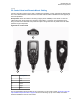
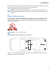
MN005720A01-AA Standard Configurations 2.2.2.5 O3 Control Head and Remote Mount Cabling Choose a mounting location for the radio, considering accessibility, control, and antenna cable lengths. The control head extension cable and the accessories cable should be installed and routed properly to avoid complications. Prerequisites: Route the cables in the wiring troughs (where available) of the vehicle or route the cables where they are protected from pinching, sharp edges, or crushing.
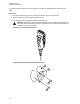
MN005720A01-AA Standard Configurations A mounting clip, which allows the control head to be mounted, is supplied together with the control head. Procedure: 1 Use the provided mounting clip to determine the location of the two screw holes. 2 Drill 7/16” deep holes for the upper and lower screws. 3 Use the tapping screw provided to install the mounting clip. CAUTION: Shield the control head (front and back) from direct exposure to pressurized water.
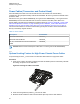
MN005720A01-AA Standard Configurations Item No. Part Number Description 1 01-80743T91 Mic Hang-Up Clip Assembly 2 03-07644M19 Screw, Machine, 8-32 x 7/16 3 - Vehicle Mounting Surface 2.2.3 Radio Locking The section describes the radio locking on the trunnion. 2.2.3.1 Locking Kit Enhanced Single Band Mobile Radio If an optional locking kit (HLN6372_) is used, position the lock housing on the trunnion after installing the radio mounting screws.
MN005720A01-AA Standard Configurations 2.3 Power Cables (Transceiver and Control Head) Route the RED power cable from both the radio and the control head to the vehicle battery compartment, using accepted industry methods and standards. Be sure to grommet the firewall hole to protect the cable.
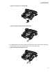
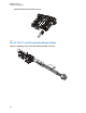
MN005720A01-AA Standard Configurations Figure 53: Installing the Locking Bracket Figure 54: Bracket Installation (Assembled State) 4 To disassemble the power cable, squeeze the locking bracket clips inward and while squeezing the clips, pull the locking clip and power cable to remove the power cable.
MN005720A01-AA Standard Configurations Figure 56: Bracket Uninstallation (2 of 2) 2.3.
MN005720A01-AA Standard Configurations Figure 58: HKN6187_ Power Cable with External Speaker Connector, Record Audio Output Jack (2.5 mm) and Earphone Jack (2.5 mm) NOTICE: Audio Out – Does not require CPS programming. Attaching a headset mutes the external speakers of the radio which are attached to the SPK jack of the control head. Record Out – Requires CPS programming. In CPS, navigate to Radio Wide/Advanced/Record Audio and select TX + RX Audio. 2.3.
MN005720A01-AA Standard Configurations Figure 59: Battery Selector Switch 2.4 Antenna Installation IMPORTANT: To ensure optimum performance and compliance with RF Energy Safety standards, these antenna installation guidelines, and instructions are limited to metal-body vehicles with appropriate ground planes and consider the potential exposure of back seat passengers and bystanders outside the vehicle.
MN005720A01-AA Standard Configurations Ensure that the antenna cable can be easily routed to the radio. Route the antenna cable as far away as possible from any vehicle electronic control units and associated wiring. Check the antenna location for any electrical interference. NOTICE: Any two metal pieces rubbing against each other such as seat springs, shift levers, trunk and hood lids, exhaust pipes, and others close to the antenna can cause severe receiver interference. 2.4.
MN005720A01-AA Standard Configurations NOTICE: • A minimum of 18 inches separation is required between the lightbar and any roof-mounted antennas to prevent interference with the lightbar circuitry (see lightbar manufacturers installation information). • LMR antennas should only be placed at the center of the roof (LOC:1) or center of the trunk (LOC:2). • To ensure compliance with RF Energy Exposure regulations, install VHF and UHF 1/4 wave antenna at LOC:1 (center of the roof only).
MN005720A01-AA Standard Configurations No. Description 4 Cable 5 Mini UHF Jack 6 RF Antenna Connector Label 2.4.3.1 Installing Mini-UHF Connection Prerequisites: • Ensure that there is sufficient slack in the antenna cable. • Ensure that the collar of the antenna cable plug is loose and does not bind. • Ensure that the mini-UHF jack is tight in the radio housing. Procedure: 1 Slide the collar back against the flange.
MN005720A01-AA Standard Configurations NOTICE: DO NOT use pliers or any other device to grip the tightening tool. It has been designed to allow you to achieve the proper torque on the collar without overtightening. Overtightening the collar can damage the connector and the radio. When you feel the tool slipping on the collar, the connection has been properly tightened. The tool can also be used to loosen a tight collar. 2.4.
MN005720A01-AA Standard Configurations Procedure: 1 To mark the mounting hole locations, use the speaker mounting bracket as a template. 2 Use the self-drilling screws provided to fasten the trunnion. 3 Attach the speaker and fasten it to the trunnion with two wing screws. 4 Route the speaker wires under the carpet or floor covering, or behind the kick panels. Ensure that the wires are out of the way of the occupants of the vehicle.
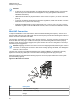
MN005720A01-AA Standard Configurations Figure 65: Removing the screws on the Control Head 3 Firmly grasp the front panel of the control head. Carefully remove the front housing assembly from the back housing assembly. Note the position of the attached flex and do not pull on it excessively. Figure 66: Removing the Control Head 4 Put the control head face down on a clean, flat surface to avoid damaging it. Do not touch the oring on the back housing.
MN005720A01-AA Standard Configurations Figure 67: Disconnecting the Speaker Connector 6 Reattach the front housing assembly to the back housing assembly. Ensure that the flex is returned to its original position and that the o-ring on the back housing assembly is not pinched. Figure 68: Reattaching the Control Head 7 Secure the front housing assembly back to the back housing assembly with four new screws using the Torx T-20 bit. Apply 9 in. lbs. torque for each screw. 2.
MN005720A01-AA Standard Configurations 2.7 RFID (Option) A mobile radio equipped with an RFID tag allows an alternate option to track the radio. Each RFID equipped radio has an RFID tag preprogrammed with the serial number (also found on the FCC label), band, and radio model information of the radio. Figure 69: RFID Location 1 No. Description 1 RFID Tag 2.7.