MN005720A01-AB Chapter 2: Standard Configurations emergency accessory is installed, the radio powers up incorrectly into emergency mode all the time. Refer to Figure 89: Emergency Jumper Removal in Remote Mount on page 86 for details. The design of the control head is different compared to the radio. Therefore it is also not necessary to attach HLN6863 to J100 to prevent accidental emergency operation.
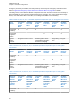
MN005720A01-AB Chapter 2: Standard Configurations Mid Power Dash/ Remote High-Power Dash/ Remote Transceiver Red Power Wire HLN6863 Thin Red Wire at J2 HLN6863 Thin Red Wire at J626 Transceiver Red Power Wire Connected to ignition switch Ignition switch controls HLN6863 Thin Red Wire at J2 HLN6863 Thin Red Wire at J626 X No ignition switch control. Enables ignition switch functionality as programmed in the codeplug.
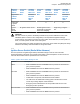
MN005720A01-AB Chapter 2: Standard Configurations Feature Description Required Soft Power-off Ignition Only Power-up • If IGNITION is not present, all transmissions are inhibited. • The radio is able to affiliate with trunking systems. The radio can ONLY receive trunking dispatch communications. • Emergency Alarm transmissions are possible with the use of the Emergency Power-up feature. • Radio POWERS ON when the Power button is pressed and Ignition is present.
MN005720A01-AB Chapter 2: Standard Configurations • For 130 W operation, parallel the two 11 Ω speakers, each rated at 65 W minimum. Proper phasing of the two speakers is important when connecting two speakers in parallel, wire similar speaker terminals together to ensure maximum loudness and prevent "deadspots". For example, if the terminals are marked "1" and "2", connect the terminals marked "1" together and connect those wires to one speaker lead.
MN005720A01-AB Chapter 2: Standard Configurations NOTICE: For optimum radio performance, orient the mounting trunnion as shown in the following figures. For new or existing installations of APX 2500, APX 4500, and APX 1500, use only the APX mobile trunnion, kit number HLN6861_. Figure 44: Enhanced Single Band Mobile Radio Trunnion Orientation 1 Applies to radios in dash and remote installations. No. Description 1 Radio Front 2.2.
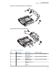
MN005720A01-AB Chapter 2: Standard Configurations Figure 45: Transmission Hump Trunnion Mounting 3 1 1 Figure 46: Below Dash Trunnion Mounting 1 3 2 7 6 1 5 4 Table 7: Mid Power Trunnion Kit Item Part Number Description Mid Power Radio 1 0305760W04 Trunnion Mounting Wing Screw Enhanced Single Band Mobile 2 0312002B14 Self-Drilling Tapping Screw Enhanced Single Band Mobile 3 HLN6861_ ASTRO Trunnion Hardware Kit Enhanced Single Band Mobile 4 - Threaded Hole for Screw - 5 - Groove
MN005720A01-AB Chapter 2: Standard Configurations Item Part Number Description Mid Power Radio 6 - Plastic Guides - 3 Using the trunnion mounting bracket as a template, mark the positions of the holes on the mounting surface. Use the innermost four holes for a curved mounting surface such as the transmission hump, and the four outermost holes for a flat surface such as under the dash. 4 Center punch the spots you have marked and realign the trunnion in position.
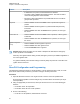
MN005720A01-AB Chapter 2: Standard Configurations 2.2.2.1.1 Installing Remote Mount Control Head Procedure: 1 Use the control unit trunnion as a template to mark the mounting holes; drill 5/32" holes. If mounting on a plastic surface, use a metal backing plate. 2 Attach the trunnion bracket using all four 10-16" x 5/8" self-tapping screws provided. 3 Temporarily install the control head (adjusting for proper viewing angle) and fasten it to the trunnion with two wing screws.
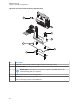
MN005720A01-AB Chapter 2: Standard Configurations Figure 48: O9 Control Head Installation Exploded View 1 6 5 2 4 3 No. Description 1 Adjust the control head to a desired angle and secure with wing screws 2 Mounting surface 3 IMPORTANT: If the trunnion is mounted on a plastic or unstable surface, use a metal backing plate (not supplied).
MN005720A01-AB Chapter 2: Standard Configurations Figure 49: O5 Control Head Rear View (Also applicable for O2, O7 and E5 Control Heads) Figure 50: O9 Control Head Rear View 2.2.2.2 Multiple Control Head Installation Install control heads in a multiple control head configuration as per the steps detailed in Installing Remote Mount Control Head on page 53. Two heads can be connected to each of the two CAN connectors on the radio, with the remaining heads connected to one or both of the first two.
MN005720A01-AB Chapter 2: Standard Configurations available CAN cable lengths. Control head ground, power and ignition sense wires (black, red, and yellow respectively) may need more length (not supplied) in installations that locate the head more than 10 feet from a power source.
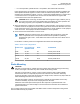
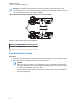
MN005720A01-AB Chapter 2: Standard Configurations Figure 51: APX Mobile O5 Control Head Front View O5 1 3 2 No. Description 1 Power button 2 Left-most Soft Menu key 3 Emergency button 3 Press the Power button to power on the control head. Figure 52: Radio Display with Current Control Head ID The head is powered on into FPP mode and displays the current control head ID number. 4 Turn the Mode knob to change the control head ID number.
MN005720A01-AB Chapter 2: Standard Configurations 2.2.2.5 O3 Control Head and Remote Mount Cabling Choose a mounting location for the radio, considering accessibility, control, and antenna cable lengths. The control head extension cable and the accessories cable should be installed and routed properly to avoid complications. Prerequisites: Route the cables in the wiring troughs (where available) of the vehicle or route the cables where they are protected from pinching, sharp edges, or crushing.
MN005720A01-AB Chapter 2: Standard Configurations A mounting clip, which allows the control head to be mounted, is supplied together with the control head. Procedure: 1 Use the provided mounting clip to determine the location of the two screw holes. 2 Drill 7/16” deep holes for the upper and lower screws. 3 Use the tapping screw provided to install the mounting clip. CAUTION: Shield the control head (front and back) from direct exposure to pressurized water.
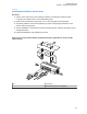
MN005720A01-AB Chapter 2: Standard Configurations Item No. Part Number Description 1 01-80743T91 Mic Hang-Up Clip Assembly 2 03-07644M19 Screw, Machine, 8-32 x 7/16 3 - Vehicle Mounting Surface 2.2.3 Radio Locking The section describes the radio locking on the trunnion. 2.2.3.1 Locking Kit Enhanced Single Band Mobile Radio If an optional locking kit (HLN6372_) is used, position the lock housing on the trunnion after installing the radio mounting screws.
MN005720A01-AB Chapter 2: Standard Configurations 2.3 Power Cables (Transceiver and Control Head) Route the RED power cable from both the radio and the control head to the vehicle battery compartment, using accepted industry methods and standards. Be sure to grommet the firewall hole to protect the cable.
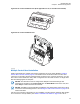
MN005720A01-AB Chapter 2: Standard Configurations Figure 59: Installing the Locking Bracket Figure 60: Bracket Installation (Assembled State) 4 To disassemble the power cable, squeeze the locking bracket clips inward and while squeezing the clips, pull the locking clip and power cable to remove the power cable.
MN005720A01-AB Chapter 2: Standard Configurations Figure 62: Bracket Uninstallation (2 of 2) 2.3.
MN005720A01-AB Chapter 2: Standard Configurations Figure 64: HKN6187_ Power Cable with External Speaker Connector, Record Audio Output Jack (2.5 mm) and Earphone Jack (2.5 mm) NOTICE: Audio Out – Does not require CPS programming. Attaching a headset mutes the external speakers of the radio which are attached to the SPK jack of the control head. Record Out – Requires CPS programming. In CPS, navigate to Radio Wide/Advanced/Record Audio and select TX + RX Audio. 2.3.
MN005720A01-AB Chapter 2: Standard Configurations Figure 65: Battery Selector Switch 2.4 Antenna Installation IMPORTANT: To ensure optimum performance and compliance with RF Energy Safety standards, these antenna installation guidelines, and instructions are limited to metal-body vehicles with appropriate ground planes and consider the potential exposure of back seat passengers and bystanders outside the vehicle.
MN005720A01-AB Chapter 2: Standard Configurations Ensure that the antenna cable can be easily routed to the radio. Route the antenna cable as far away as possible from any vehicle electronic control units and associated wiring. Check the antenna location for any electrical interference. NOTICE: Any two metal pieces rubbing against each other such as seat springs, shift levers, trunk and hood lids, exhaust pipes, and others close to the antenna can cause severe receiver interference. 2.4.
MN005720A01-AB Chapter 2: Standard Configurations NOTICE: • A minimum of 18 inches separation is required between the lightbar and any roof-mounted antennas to prevent interference with the lightbar circuitry (see lightbar manufacturers installation information). • LMR antennas should only be placed at the center of the roof (LOC:1) or center of the trunk (LOC:2). • To ensure compliance with RF Energy Exposure regulations, install VHF and UHF 1/4 wave antenna at LOC:1 (center of the roof only).
MN005720A01-AB Chapter 2: Standard Configurations Figure 67: Mini-UHF Connection 1 2 3 5 6 4 No. Description 1 Coax Conductor Plug (Pin) 2 Collar Pulled Back to Flange 3 Flange 4 Cable 5 Mini UHF Jack 6 RF Antenna Connector Label 2.4.3.1 Installing Mini-UHF Connection Prerequisites: • Ensure that there is sufficient slack in the antenna cable. • Ensure that the collar of the antenna cable plug is loose and does not bind. • Ensure that the mini-UHF jack is tight in the radio housing.
MN005720A01-AB Chapter 2: Standard Configurations Figure 68: Mini-UHF Connector Tool 3 2 1 No. Description 1 Squeeze Firmly Together 2 Tighten 3 HLN6695_ 7 Slide the tool up onto the knurled collar of the plug. 8 Squeeze the two straight legs of the tool firmly together between your thumb and index finger and turn clockwise (as shown) to tighten the collar. It should take 1/4 turn or less. NOTICE: DO NOT use pliers or any other device to grip the tightening tool.
MN005720A01-AB Chapter 2: Standard Configurations 2.4.6 GPS/GLONASS and Wi-Fi Antenna Connection Connect GPS and Wi-Fi antenna cable QMA plug to the radio QMA jack for GPS and Wi-Fi respectively. Figure 69: GPS/GLONASS and Wi-Fi Antenna Connector on the radio 2.5 Installing the Speaker The speaker kit includes a trunnion bracket that allows the speaker to be mounted in various ways. With the trunnion bracket, the speaker can mount permanently on the mounting surface or in accessible firewall areas.