
Installation Instructions

• For 130 W operation, parallel the two 11 Ω speakers, each rated at 65 W minimum.
Proper phasing of the two speakers is important when connecting two speakers in parallel, wire
similar speaker terminals together to ensure maximum loudness and prevent "deadspots". For
example, if the terminals are marked "1" and "2", connect the terminals marked "1" together and
connect those wires to one speaker lead. Connect the terminals marked "2" together and
connect those wires to the other speaker lead.
CAUTION: Before continuing, remember that under a high-line supply condition (16.6 V),
up to 30% more power goes to the speakers after reconfiguring for 130 W operation. Do
this setting only when your PA speakers can handle the extra power.
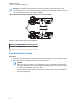
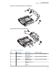
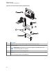
4 When the Siren/PA is configured for dual speaker for 130 W operation, it is necessary to remove
a resistor and move two jumpers to set the correct power level. Remove the Siren/PA cover, and
locate resistor R219 (0 Ω). This resistor should be removed for 130 W operation. Locate jumpers
JU100 and JU101. These jumpers should be installed for 130 W operation.
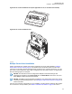
5 Close and reconnect the Siren/PA connector cover.
NOTICE: Jumpers JU100 and JU101 do not affect the Siren output level. JU100 and
JU101 compensate for the lower speaker load and the two speakers in parallel by
decreasing the gain U102-1. JU100 affects the radio PA level and JU101 affects the PA
audio level.
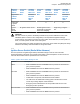
Pin locations of various power level configurations are listed in the following table.
Table 6: Power Level Configurations
Power Level Pin Location of
Speaker Leads
R219 JU100/JU101
65 W 20, 28 IN Across pins A and B
75 W 20, 36 IN Across pins A and B
100 W 20, 35 IN Across pins A and B
130 W 20, 28 OUT Across pins B and C
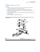
2.2
Radio Mounting
CAUTION:
DO NOT mount the radio on a plastic mounting surface without first reinforcing the mounting
surface; the weight of the radio may crack or break the mounting surface.
DO NOT mount the radio on a flat or concave surface where the radio could be partially
submersed in water. It is especially important if the cab area of the vehicle is cleaned by
spraying it with water. If the radio sits in water for a length of time, moisture may seep inside the
radio and damage the electronic components.
DO NOT allow water to stand in recessed areas of vertically mounted radios. Remove any
moisture immediately to prevent it from seeping down into the radio.
Shield the control head (front and back) from direct exposure to pressurized water. The
pressurized water from a hose usually is more severe than the stated test and conditions in
typical environments.
The mounting location must be accessible and visible. Select a location that permits routing the RF
antenna cable as directly as possible.
MN005720A01-AB
Chapter 2: Standard Configurations
49