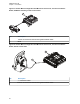
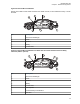
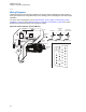
MN005720A01-AB Chapter 1: Introduction Figure 21: Remote Mount Configuration with Mid Power Transceiver, Transceiver Interface Board, CHIB Rear Assembly, and O7 Control Head 1 2 2 2 No. Description 1 ASTRO 25 Subscribers Enhanced Single Band Mobile Radio 2 MMP Figure 22: Remote Mount Configuration with Mid Power Transceiver, Transceiver Interface Board, and O9 Control Head 2 1 No.
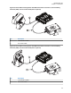
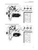
MN005720A01-AB Chapter 1: Introduction Figure 23: Remote Mount Configuration with Mid Power Radio Transceiver, Universal Relay Controller (URC), and O7 Control Head (URC is optional) 1 2 No. Description 1 17 ft Extension Cable 2 O7 to URC Cable Figure 24: Remote Mount Configuration with Mid Power Radio Transceiver, Universal Relay Controller (URC), and O9 Control Head (URC is optional) 1 2 No.
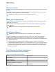
MN005720A01-AB Chapter 1: Introduction 1.2.3 Multi Control Head The multi control head option allows separate, remotely operated control heads to operate and control the radio. For example, a fire truck could have a control head located in the cab and on the rear of the truck so that the radio could be operated from outside the vehicle. NOTICE: The dual control head can be used together in the future. 1.
MN005720A01-AB Chapter 1: Introduction Tool Part Number RF antenna tool HLN6695_ Wing screw torque tool HLN6970_ 31
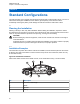
MN005720A01-AB Chapter 2: Standard Configurations Chapter 2 Standard Configurations The radio operates only in negative ground electrical systems with a valid operating range of 10.8–16.3 VDC. Before starting the installation, ensure that the ground polarity of the vehicle is correct. Accidentally reversing the polarity could damage the radio and cause the cable fuses to blow. 2.1 Planning the Installation Planning is the key to fast, easy radio installation.
MN005720A01-AB Chapter 2: Standard Configurations Figure 26: Remote Mount Installation Remote mount radio control heads mounted in the middle console, on the transmission hump, or under the dash. 5 3 1 911 2 5 4 No. Description 1 Antenna ¼-Wavelength 2 Radio 3 Speaker 4 Battery 5 Control Head Figure 27: Remote Mount Installation for Radio with O9 Control Head and Universal Relay Controller (URC is optional) 5 3 1 2 8 6 911 4 No.
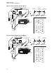
MN005720A01-AB Chapter 2: Standard Configurations 2.1.2 Wiring Diagrams The following figures show the wiring diagrams for all the possible configurations. Identify which of these figures shows the configuration that you are installing, and use the diagram when planning the installation.
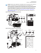
MN005720A01-AB Chapter 2: Standard Configurations Figure 29: Radio Installation (O3 Dash Mount) BATTERY (+) FUSE RED LEAD (-) FUSE HORN RELAY LIGHT RELAY SPEAKER IGN SENSE (ACC) DC POWER CABLE P2 (SEE J2 PINOUT) MIC CLIP TRUNNION ANTENNA CONNECTION ANTENNA CONNECTION 20 MOUNTING SCREW DASHMOUNT RADIO ANTENNA CONNECTION J2 REAR ACCESSORY CONNECTOR SPKR+ SPKR- VIPOUT 2 12V (RELAY) IGN SENSE (ACC) VIPOUT 1 12V (RELAY) 26 MIC ANTENNA 3 GPS (OPTIONAL) 3 ft 3 ft FIREWALL HOLE FUSE BLOCK
MN005720A01-AB Chapter 2: Standard Configurations Figure 31: Radio Installation (E5 Dash Mount) BATTERY (+) FUSE RED LEAD (-) FUSE HORN RELAY LIGHT RELAY SPEAKER IGN SENSE (ACC) ANTENNA CONNECTION DC POWER CABLE P2 (SEE J2 PINOUT) MIC CLIP ANTENNA CONNECTION ANTENNA CONNECTION J2 REAR ACCESSORY CONNECTOR TRUNNION 20 SPKR+ SPKR- VIPOUT 2 12V (RELAY) IGN SENSE (ACC) VIPOUT 1 12V (RELAY) 26 MOUNTING SCREW MIC ANTENNA 3 GPS (OPTIONAL) 3 ft 3 ft FIREWALL HOLE FUSE BLOCK ANTENNA 2 WI-FI
MN005720A01-AB Chapter 2: Standard Configurations NOTICE: In dash mount configuration, it is mandatory that a rear accessory cable is attached to the back of a mid power radio, to ground the Emergency pin to ground (GND). Or, an emergency footswitch or pushbutton switch must be attached to the back of a mid power radio.