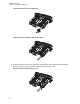
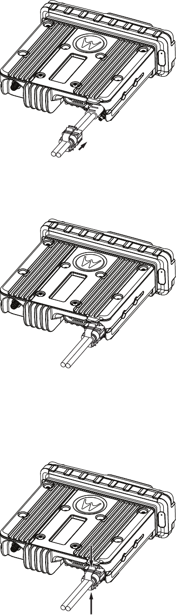
MN005720A01-AB Chapter 2: Standard Configurations Figure 59: Installing the Locking Bracket Figure 60: Bracket Installation (Assembled State) 4 To disassemble the power cable, squeeze the locking bracket clips inward and while squeezing the clips, pull the locking clip and power cable to remove the power cable.
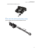
MN005720A01-AB Chapter 2: Standard Configurations Figure 62: Bracket Uninstallation (2 of 2) 2.3.
MN005720A01-AB Chapter 2: Standard Configurations Figure 64: HKN6187_ Power Cable with External Speaker Connector, Record Audio Output Jack (2.5 mm) and Earphone Jack (2.5 mm) NOTICE: Audio Out – Does not require CPS programming. Attaching a headset mutes the external speakers of the radio which are attached to the SPK jack of the control head. Record Out – Requires CPS programming. In CPS, navigate to Radio Wide/Advanced/Record Audio and select TX + RX Audio. 2.3.
MN005720A01-AB Chapter 2: Standard Configurations Figure 65: Battery Selector Switch 2.4 Antenna Installation IMPORTANT: To ensure optimum performance and compliance with RF Energy Safety standards, these antenna installation guidelines, and instructions are limited to metal-body vehicles with appropriate ground planes and consider the potential exposure of back seat passengers and bystanders outside the vehicle.
MN005720A01-AB Chapter 2: Standard Configurations Ensure that the antenna cable can be easily routed to the radio. Route the antenna cable as far away as possible from any vehicle electronic control units and associated wiring. Check the antenna location for any electrical interference. NOTICE: Any two metal pieces rubbing against each other such as seat springs, shift levers, trunk and hood lids, exhaust pipes, and others close to the antenna can cause severe receiver interference. 2.4.
MN005720A01-AB Chapter 2: Standard Configurations NOTICE: • A minimum of 18 inches separation is required between the lightbar and any roof-mounted antennas to prevent interference with the lightbar circuitry (see lightbar manufacturers installation information). • LMR antennas should only be placed at the center of the roof (LOC:1) or center of the trunk (LOC:2). • To ensure compliance with RF Energy Exposure regulations, install VHF and UHF 1/4 wave antenna at LOC:1 (center of the roof only).
MN005720A01-AB Chapter 2: Standard Configurations Figure 67: Mini-UHF Connection 1 2 3 5 6 4 No. Description 1 Coax Conductor Plug (Pin) 2 Collar Pulled Back to Flange 3 Flange 4 Cable 5 Mini UHF Jack 6 RF Antenna Connector Label 2.4.3.1 Installing Mini-UHF Connection Prerequisites: • Ensure that there is sufficient slack in the antenna cable. • Ensure that the collar of the antenna cable plug is loose and does not bind. • Ensure that the mini-UHF jack is tight in the radio housing.
MN005720A01-AB Chapter 2: Standard Configurations Figure 68: Mini-UHF Connector Tool 3 2 1 No. Description 1 Squeeze Firmly Together 2 Tighten 3 HLN6695_ 7 Slide the tool up onto the knurled collar of the plug. 8 Squeeze the two straight legs of the tool firmly together between your thumb and index finger and turn clockwise (as shown) to tighten the collar. It should take 1/4 turn or less. NOTICE: DO NOT use pliers or any other device to grip the tightening tool.
MN005720A01-AB Chapter 2: Standard Configurations 2.4.6 GPS/GLONASS and Wi-Fi Antenna Connection Connect GPS and Wi-Fi antenna cable QMA plug to the radio QMA jack for GPS and Wi-Fi respectively. Figure 69: GPS/GLONASS and Wi-Fi Antenna Connector on the radio 2.5 Installing the Speaker The speaker kit includes a trunnion bracket that allows the speaker to be mounted in various ways. With the trunnion bracket, the speaker can mount permanently on the mounting surface or in accessible firewall areas.
MN005720A01-AB Chapter 2: Standard Configurations Figure 70: Speaker Mounting 1 2 3 4 No. Description 1 Trunnion Bracket 2 Firewall 3 Dashboard 4 EITHER way 2.5.1 Internal Speaker Disassembly Prerequisites: NOTICE: This configuration is only applicable for O2 Control Heads. Procedure: 1 Unplug the power, antenna, microphone, and all accessories connections. If the radio is a remote-mount radio, disconnect the remote-mount control cable from the front of the transceiver.
MN005720A01-AB Chapter 2: Standard Configurations Figure 71: Removing the screws on the Control Head 3 Firmly grasp the front panel of the control head. Carefully remove the front housing assembly from the back housing assembly. Note the position of the attached flex and do not pull on it excessively. Figure 72: Removing the Control Head 4 Put the control head face down on a clean, flat surface to avoid damaging it. Do not touch the oring on the back housing.
MN005720A01-AB Chapter 2: Standard Configurations Figure 73: Disconnecting the Speaker Connector 6 Reattach the front housing assembly to the back housing assembly. Ensure that the flex is returned to its original position and that the o-ring on the back housing assembly is not pinched. Figure 74: Reattaching the Control Head 7 Secure the front housing assembly back to the back housing assembly with four new screws using the Torx T-20 bit. Apply 9 in. lbs. torque for each screw. 2.
MN005720A01-AB Chapter 2: Standard Configurations 2.7 RFID (Option) A mobile radio equipped with an RFID tag allows an alternate option to track the radio. Each RFID equipped radio has an RFID tag preprogrammed with the serial number (also found on the FCC label), band, and radio model information of the radio. Figure 75: RFID Location 1 No. Description 1 RFID Tag 2.7.
MN005720A01-AB Chapter 2: Standard Configurations No. Descrption 1 RFID Tag 2 Read Angle Figure 77: Tag Angle for Enhanced Single Band Mobile Radio 2 1 No. Descrption 1 RFID Tag 2 Tag Angle Figure 78: Examples of Reader and Tag Aligned (Reader Orientation) 1 1 2 2 Figure 79: Example of Reader and Tag Misalignment (Reader Orientation) 1 2 No.
MN005720A01-AB Chapter 2: Standard Configurations No. Descrption 2 Tag 2.7.2 Programming RFID (If Equipped) Reprogram the tag (up to 12 ASCII characters when encoded to hexadecimal format) by using any UHF Gen 2 capable RFID writer, for example, Motorola Solutions MC9090-G. NOTICE: Follow the read direction in RFID Reading on page 74 to optimize reprogramming.
MN005720A01-AB Chapter 2: Standard Configurations 2.8 Completing the Installation Follow the following steps to complete the installation. Procedure: 1 Connect the speaker to the accessory cable. 2 Verify that the ignition sense wire is attached according to planned ignition sense. 3 Attach the accessory cable into J600. 4 Verify that the control head is attached to either the TIB or the CAN extension cable. 5 Attach the power cable to the back of the transceiver.
MN005720A01-AB Chapter 3: Universal Relay Controller Installation Chapter 3 Universal Relay Controller Installation The Universal Relay Controller (URC) is an extension of an orderable accessory for O7 or O9 control head. URC is used to control high power switching peripherals, for example, lightbar. URC works on all power application controlled lightbars. URC is connected to the transceiver GCAI port. The URC design consists of a microcontroller and uses ten relays to control the switching device.
MN005720A01-AB Chapter 3: Universal Relay Controller Installation Procedure: 1 Use the URC trunnion as a template to mark the mounting holes. Then, drill 5/32 in. holes. If mounting on a plastic surface, use a metal backing plate. 2 Attach the trunnion bracket using all four 10 – 16 in. x 5/8 in. self-tapping screws provided. 3 Temporarily install the URC (adjust for proper viewing angle) and fasten it to the trunnion with two wing screws.
MN005720A01-AB Chapter 3: Universal Relay Controller Installation No. Description 6 Adjust the universal relay controller to desired angle and secure with wing screws 3.2 O7/O9 Universal Relay Controller Cable Assembly This sections provides the instruction for URC cable assembly. 3.2.1 Installing the Power Cable Procedure: 1 Remove the cap nut of power cable gland assembly, and insert the power cable through the cap nut and neoprene seal in the cable gland body.
MN005720A01-AB Chapter 3: Universal Relay Controller Installation Figure 82: Power and Ground Cable Glands 2 1 No. Description 1 Ground Cable Gland 2 Power Cable Gland Figure 83: Cable Gland Assembly with Gasket 5 1 4 2 3 No. Description 1 Cable Gland Body 2 Neoprene Seal 3 Cap Nut 4 Gasket, Cable Gland 5 Counter Nut 3.2.3 Installing the Wires Procedure: 1 Assemble the wires into the lightbar gasket retainer and lightbar gasket.
MN005720A01-AB Chapter 3: Universal Relay Controller Installation 2 Each individual loose wire (before stripping off the wire jacket) is inserted one at a time through the chassis. Ensure that the lightbar wire is straight before inserting the wire into the chassis. The radial gasket seals each of the wire individually. When a thick wire (for example AWG 14 wire or wire OD > 2.90 mm) is inserted through the chassis, there is potential tearing at the rubber gasket. Remove the rubber gasket residual.
MN005720A01-AB Chapter 3: Universal Relay Controller Installation No. Description 1 Black Stick 4 Cover the lightbar gasket retainers hole with seal, gasket, and ground cable gland, if no wire is inserted. 5 The lightbar gasket should be replaced at each reassembly of the wire. NOTICE: Use of other cable gauges except as recommended in this manual may result in water intrusion. Any reassembly of wire needs a new lightbar gasket replaced.
MN005720A01-AB Chapter 4: Options and Accessories Installation Chapter 4 Options and Accessories Installation This chapter provides the options and accessories installation for dash mounted and remote mounted configurations. 4.1 Dash-Mount Accessory Installation For dash-mounted configurations, the accessories must be installed through the accessory connector assembly that is on the rear of the radio, next to the power connector.
MN005720A01-AB Chapter 4: Options and Accessories Installation CAUTION: The radio is sold with correct accessory cables and jumpers to have emergency deactivated by default, regardless of the setting in Customer Programming Software (CPS). However, if cables are not used, or if jumpers are removed without replacing with an emergency accessory button/switch at one of the accessory ports, the radio powers up upon the application of A+.
MN005720A01-AB Chapter 4: Options and Accessories Installation 3 Attach wires from the accessory to the appropriate wire on the VIP cable (see Table 13: VIP Output Connections on page 91 and Table 14: VIP Input Connections on page 92). CAUTION: The radio is sold with correct accessory cables and jumpers to have emergency de-activated by default, regardless of the setting in Customer Programming Software (CPS).
MN005720A01-AB Chapter 4: Options and Accessories Installation 7 Reassemble the TIB following the Basic Service Manual procedure. Use 6-8 in-lbs torque on each screw. Remember to include the TIB O-ring gasket. 8 Reattach the TIB flex. 9 Reattach the TIB to the radio transceiver. 10 To secure the TIB to the radio transceiver, apply 6-8 in-lbs of torque to each screw . 4.2.2 Horn (External Alarm) Relay Installation Mount the horn relay in a suitable location (normally under the dash).
MN005720A01-AB Chapter 4: Options and Accessories Installation Figure 90: Gunlock Switch Redundancy Diagram Car Battery GND Redundancy Wiring Transceiver and control head Momentary or time-out bypass manual switch GND Gunlock VIP Cable GND VIP OUT 4.2.5 Horn-Ring Transfer Configure the Horn Relay for either Negative Contact or Positive Contact as shown in “section 6.3” of the siren/PA manual (6881093C18).
MN005720A01-AB Chapter 4: Options and Accessories Installation Figure 91: Siren/PA Horn-Ring Connections Under Hood Horn Relay Horn Break Here Horn Ring + 12V + 12V N.C. To Control Head VIP Input Programmed for Horn-Ring N.C. N.O. N.O. To Control Head VIP Output Programmed for Horn-Ring Transfer To Control Head VIP Output Programmed for Horn-Ring Transfer To Horn COM. COM. To SW B+ at VIP Connector Break Here Horn Ring To DIG.
MN005720A01-AB Chapter 4: Options and Accessories Installation 4.2.9 RS232 Cables RS232 cables are not compatible with Customer Programming Software (CPS) radio reading or programming, but can be used for interfacing with RS232 accessories or RS232 computer programs. HKN6122_ is an RS232 serial COM port computer interface cable from J600 connector.
MN005720A01-AB Chapter 4: Options and Accessories Installation Configuration on page 96 and Figure 99: Rear Accessory Connector Data Configuration on page 96, respectively. Use these connections to wire control relays. One end of the relay should connect to switched B+ voltage, while the other side connects to a software controlled ON/OFF switch inside the control head. The relay can be normally on or normally off depending on the configuration of the VIP outputs.
MN005720A01-AB Chapter 4: Options and Accessories Installation 4.3.2 VIP Input Connections The VIP input pins are only available on the back of the control head (remote mount). These connections control inputs from switches. One side of the switch connects to ground while the other side connects to a buffered input on the control head. The switch can be normally closed (NC) or normally open (NO) depending on the configuration of the VIP inputs.
MN005720A01-AB Chapter 4: Options and Accessories Installation No. Description 1 Siren Cable 2 Remove the knob from the siren/PA cable connector. 3 Remove all four screws from the connector in the siren/PA cable. 4 Open the connector cap and locate pin 8. 5 Using the contact removal tool (6684690C02), remove pin 8 from the connector. 6 Put the connector cap in place and proceed to reinstall the four screws and the knob.
MN005720A01-AB Chapter 4: Options and Accessories Installation 4.5.1 Disassembly and Assembly This section provides the detailed disassembly and reassembly information. 4.5.1.1 Disassembly Procedure: 1 Disconnect the negative terminal from the vehicle battery. Make sure that the battery cable is secured such that it cannot power the vehicle electrical system. 2 Unscrew both jackscrews completely. 3 Pull the accessory connector assembly out from the radio.
MN005720A01-AB Chapter 4: Options and Accessories Installation Figure 97: Exploded View of Accessory Connector Assembly (HLN6863_) 5 Squeeze the covers together bending the wires in the strain-relief features. You may need a pair of pliers to seat the assembly covers. 6 Once the covers are fully seated, fasten them with the cover screws. Tighten the screws firmly but do not over-tighten them. Be sure that none of the wires are pinched.
MN005720A01-AB Chapter 4: Options and Accessories Installation Figure 98: Rear Accessory Connector Audio Configuration 2 4 1 3 8 7 15 5 6 14 13 Description 1 GND 2 SPKR LO- 3 SPKR HI+ 4 IGNITION 5 SWB+ 6 VIP OUT 2 7 EMER 8 N.C. 9 MIC HI 10 PTT 11 VIP OUT 1 12 DISC. AUD 7 3 4 12 11 2 10 11 9 8 5 8 No.
MN005720A01-AB Chapter 4: Options and Accessories Installation No. Description 3 SPKR HI+ 4 IGNITION 5 SWB+ 6 VIP OUT 2 7 EMER 8 CTS-ASTRO RTS_DCE 9 RTS- ASTRO CTS_DCE 10 BUS+ 11 TX-ASTRO RX_DCE 12 VIP OUT 1 13 RX-ASTRO RX_DCE 14 BUS- 15 BUSY You must attach the correct adapter. Installing the wrong adapter may damage the data communication circuitry inside your radio.
MN005720A01-AB Chapter 5: Motorcycle Radio Installation Chapter 5 Motorcycle Radio Installation This chapter covers the motorcycle radio installation. The motorcycle radio installation is not applicable for APX 4500/APX 1500 radios and O9 control heads. 5.1 Motorcycle Radio Description The motorcycle model includes all the same components in the standard radio, with the exceptions listed in the model charts in the Enhanced Single Band Mobile Radio Basic Service Manual (MN005718A01). 5.1.
MN005720A01-AB Chapter 5: Motorcycle Radio Installation 5.1.4 Microphone A weather-resistant, palm microphone, and coiled cord plug into a pigtail connector on the control cable. The microphone attaches to a hang-up bracket located within easy reach of the motorcycle rider. The coiled cord is long enough to be operated by someone standing next to the motorcycle, yet short enough to not interfere with the motorcycle steering or operation. 5.1.5 External Speaker A 3.
MN005720A01-AB Chapter 5: Motorcycle Radio Installation • Mounting the universal mounting plate and related hardware at the rear of the motorcycle. • Mounting the control head, speaker, microphone, and related hardware forward on the motorcycle. • Routing the power cable, control-head cable, speaker cable, and ignition sense cable to the weather-resistant enclosure. • Mounting the weather-resistant enclosure and radio chassis, and connecting the cables.
MN005720A01-AB Chapter 5: Motorcycle Radio Installation • Direct access to the microphone should be provided from both sides of the motorcycle. • Sufficient slack in the microphone coiled cord should be allowed so as not to impede steering. • Mounting hardware must be stainless steel to prevent corrosion. • If an extra length of cable is used to extend the microphone, ensure that the added capacitance does not interfere with the operation of the radio.
MN005720A01-AB Chapter 5: Motorcycle Radio Installation 5.3 Universal Mounting Plate The universal mounting plate, supplied with the motorcycle radio, must be mounted on the motorcycle first. It provides the base for the weather-resistant enclosure to be mounted. The method used for mounting the plate depends on the make and model of the motorcycle and whether the plate is mounted to a carrier or to the motorcycle chassis.
MN005720A01-AB Chapter 5: Motorcycle Radio Installation 5.4 Speaker and Control Head Installation NOTICE: To disable the internal speaker of the O2 Control Head, refer to Internal Speaker Disassembly on page 71. The control head mounting location and configuration is determined largely by the make and model of motorcycle. Two different mounting configurations are described below.
MN005720A01-AB Chapter 5: Motorcycle Radio Installation Figure 102: Handlebar Installation with Speaker and Control Head Mounted Together Provision has been made on the combination speaker/control-head bracket for mounting the microphone hang-up clip. If that mounting is desired, the hang-up clip must be attached to the bracket before installing the control head and speaker. See Microphone Hang-Up Clip on page 73 for the hangup clip procedure. 5.4.1.
MN005720A01-AB Chapter 5: Motorcycle Radio Installation 5.4.2 Fuel Tank Console Installation with Speaker and Control Head Mounted Together Some motorcycles provide a console for mounting radio equipment. This console is attached to the top of the fuel tank. With the use of a mounting bracket, screws, nuts, and lock washers, the combination speaker/control-head bracket can be mounted to this console.
MN005720A01-AB Chapter 5: Motorcycle Radio Installation 5.4.3 Handlebar Installation with Speaker and Control Head Mounted Separately It may be necessary to use the smaller control head bracket (part number 0780127N02) and mount the speaker and microphone hang-up clip in another location on the motorcycle. Temporarily fasten the control-head end of the control-head cable to the control head. Also, fasten the control head to its bracket before installing the control head using the described bracket.
MN005720A01-AB Chapter 5: Motorcycle Radio Installation 5.4.3.1 Installing Handlebar with Speaker and Control Head Mounted Separately Follow the procedure when mounting the smaller control-head bracket. Procedure: 1 Determine the location to mount the control head. Choose a location that is not only mechanically convenient, but is located for ease of operation. 2 Securely mount the Motorola Solutions-supplied spacers, mic-cable bracket, and small controlhead bracket to the handlebars.
MN005720A01-AB Chapter 5: Motorcycle Radio Installation Figure 105: Fuel Tank Console Installation with Speaker and Control Head Mounted Separately 108
MN005720A01-AB Chapter 5: Motorcycle Radio Installation Installation is the same as detailed in Fuel Tank Console Installation with Speaker and Control Head Mounted Together on page 105 and Installing Handlebar with Speaker and Control Head Mounted Separately on page 107. 5.5 Installing the Speaker Follow the procedure when the speaker is mounted separately from the control head.
MN005720A01-AB Chapter 5: Motorcycle Radio Installation 4 Torque nuts to 20 in-lbs torque. 5.6.2 Speaker/Control Head Bracket Side Mounting Follow the procedure for the speaker/control head bracket side mounting. Procedure: 1 Attach the hang-up clip to the left side of the speaker/control-head bracket using two machine screws, lock washers, and nuts as shown in Figure 102: Handlebar Installation with Speaker and Control Head Mounted Together on page 104. 2 Torque nuts to 20 in-lbs. torque. 5.6.
MN005720A01-AB Chapter 5: Motorcycle Radio Installation align to. Refer to band markings on radio for the proper antenna port location. For the GPS antenna, use the 5/8-inch hole near the front of the housing near the lock. Figure 106: Location of Antenna Port 5 1 2 3 4 No.