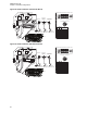
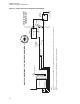
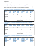
MN005720A01-AB Chapter 2: Standard Configurations Figure 35: Radio Installation (O5 Remote Mount) BATTERY (+) (-) FUSE PORTS ON REAR OF REMOTE CONTROL HEAD RED LEAD FUSE FUSE YELLOW BLOCK LEAD ANTENNA 1 FUSE HORN RELAY BLACK LEAD LIGHT RELAY SPEAKER ANTENNA 2 WI-FI (OPTIONAL) 3 ft ACC ANTENNA 3 GPS (OPTIONAL) PWR SPK CAN CAN 10 9 8 7 5 4 2 CONTROL HEAD MIC FIREWALL HOLE DC POWER CABLE USB VIP CONNECTOR PIN-OUT 3 ft MIC CLIP DEK VIP J400 6 J400 1 VIPCable Radio Function Pin
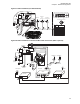
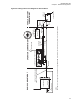
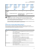
MN005720A01-AB Chapter 2: Standard Configurations Figure 37: Radio Installation (O7 Remote Mount) FUSE BATTERY (+) PORTS ON REAR OF REMOTE CONTROL HEAD RED LEAD FUSE (-) FUSE YELLOW BLOCK LEAD ANTENNA 1 FUSE HORN RELAY BLACK LEAD 3 ft LIGHT RELAY SPEAKER ANTENNA 2 WI-FI (OPTIONAL) ACC ANTENNA 3 GPS (OPTIONAL) PWR SPK CAN CAN 10 9 MIC J400 4 2 MIC CLIP 6 7 5 FIREWALL HOLE DC POWER CABLE USB VIP CONNECTOR PIN-OUT 3 ft 8 CONTROL HEAD DEK VIP J400 1 VIPCable Radio Function Pi
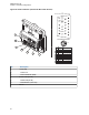
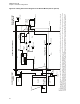
MN005720A01-AB Chapter 2: Standard Configurations Figure 39: Radio Installation (O9 Remote Mount with Pinouts) J2 REAR ACCESSORY CONNECTOR 20 SPKR+ 26 7 13 SPKR- VIPOUT 2 12V (RELAY) IGN SENSE (ACC) VIPOUT 1 12V (RELAY) EMERGENCY 21 1 14 1 VIP CONNECTOR PIN-OUT 2 10 9 8 7 5 4 2 3 6 J400 1 Radio VIP Cable Function Pin (HKN6196_) Number Wire Color J400-1 RED SWB + 4 5 6 No. Description 1 J500 USB 2 J100 M.A.
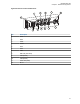
MN005720A01-AB Chapter 2: Standard Configurations Figure 40: Remote Control Head Pinouts 5 4 3 2 6 1 12 No. Description 1 J100 2 J200 3 J300L 4 J300R 5 J400 6 J500 7 USB 8 DEK VIP (YELLOW) 9 CAN (BLUE) 10 CAN (BLUE) 11 PWR SPK (RED) 12 M.A.
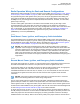
42 MICROPHONE SPEAKER A+ (RED) IGN SENSE (thin RED) FUSE SEE NOTE ACC line VEHICLE IGNITION SWITCH Ignition sense cable uses either 3-amp fuse (6580283E01) or 4-amp fuse (6580283E02) NOTE: See TABLE 2-1 for wiring of the thin RED wire. A good GROUND connection to the car chassis is required for correct radio opearaions.
GROMMET SPEAKER CONTROL HEAD (REAR VIEW) A+ (RED) IGN SENSE (YELLOW) MICROPHONE OPERATOR COMPARTMENT FUSE SEE NOTE ACC line VEHICLE IGNITION SWITCH NOTE: See TABLE 2-1 for wiring of the YELLOW wire. A good GROUND connection to the car chassis is required for correct radio operation.
44 URC Controller Box REAR CONNECTOR RADIO GCAI to RJ45 Cable Chassis GND (BLK) GROMMET CAN extension cable (BLK) IGN Sense (yellow) A+ (Red) 16A Circuit Breaker 15A, 20A OR 30A FUSE SPEAKER SEE NOTE A+ (Red) ON/ACC VEHICLE IGNITION SWITCH 3A OR 4A FUSE MICROPHONE 15A Fuse RADIO POWER CABLE (RED/BATTERY HOT) Control Head (Rear View) A+ (Red) OPERATOR COMPARTMENT GROMMET (-) VEHICLE BATTERY Chassis GND GROMMET (+) PART OF VEHICLE WIRING Siren Speaker VEHICLE BATTERY COMPARTMEN
MN005720A01-AB Chapter 2: Standard Configurations 2.1.3 Radio Operation Wiring for Dash and Remote Configurations Determine the radio functionality you wish to achieve from the tables in Remote Mount: Power, Ignition, and Emergency Cable Installation on page 45, which is the vehicle ignition switch state is controlling, the physical wiring of the radio ignition sense (ACC) wire, and by the programmed CPS setting.
MN005720A01-AB Chapter 2: Standard Configurations emergency accessory is installed, the radio powers up incorrectly into emergency mode all the time. Refer to Figure 89: Emergency Jumper Removal in Remote Mount on page 86 for details. The design of the control head is different compared to the radio. Therefore it is also not necessary to attach HLN6863 to J100 to prevent accidental emergency operation.
MN005720A01-AB Chapter 2: Standard Configurations Mid Power Dash/ Remote High-Power Dash/ Remote Transceiver Red Power Wire HLN6863 Thin Red Wire at J2 HLN6863 Thin Red Wire at J626 Transceiver Red Power Wire Connected to ignition switch Ignition switch controls HLN6863 Thin Red Wire at J2 HLN6863 Thin Red Wire at J626 X No ignition switch control. Enables ignition switch functionality as programmed in the codeplug.
MN005720A01-AB Chapter 2: Standard Configurations Feature Description Required Soft Power-off Ignition Only Power-up • If IGNITION is not present, all transmissions are inhibited. • The radio is able to affiliate with trunking systems. The radio can ONLY receive trunking dispatch communications. • Emergency Alarm transmissions are possible with the use of the Emergency Power-up feature. • Radio POWERS ON when the Power button is pressed and Ignition is present.
MN005720A01-AB Chapter 2: Standard Configurations • For 130 W operation, parallel the two 11 Ω speakers, each rated at 65 W minimum. Proper phasing of the two speakers is important when connecting two speakers in parallel, wire similar speaker terminals together to ensure maximum loudness and prevent "deadspots". For example, if the terminals are marked "1" and "2", connect the terminals marked "1" together and connect those wires to one speaker lead.
MN005720A01-AB Chapter 2: Standard Configurations NOTICE: For optimum radio performance, orient the mounting trunnion as shown in the following figures. For new or existing installations of APX 2500, APX 4500, and APX 1500, use only the APX mobile trunnion, kit number HLN6861_. Figure 44: Enhanced Single Band Mobile Radio Trunnion Orientation 1 Applies to radios in dash and remote installations. No. Description 1 Radio Front 2.2.
MN005720A01-AB Chapter 2: Standard Configurations Figure 45: Transmission Hump Trunnion Mounting 3 1 1 Figure 46: Below Dash Trunnion Mounting 1 3 2 7 6 1 5 4 Table 7: Mid Power Trunnion Kit Item Part Number Description Mid Power Radio 1 0305760W04 Trunnion Mounting Wing Screw Enhanced Single Band Mobile 2 0312002B14 Self-Drilling Tapping Screw Enhanced Single Band Mobile 3 HLN6861_ ASTRO Trunnion Hardware Kit Enhanced Single Band Mobile 4 - Threaded Hole for Screw - 5 - Groove
MN005720A01-AB Chapter 2: Standard Configurations Item Part Number Description Mid Power Radio 6 - Plastic Guides - 3 Using the trunnion mounting bracket as a template, mark the positions of the holes on the mounting surface. Use the innermost four holes for a curved mounting surface such as the transmission hump, and the four outermost holes for a flat surface such as under the dash. 4 Center punch the spots you have marked and realign the trunnion in position.
MN005720A01-AB Chapter 2: Standard Configurations 2.2.2.1.1 Installing Remote Mount Control Head Procedure: 1 Use the control unit trunnion as a template to mark the mounting holes; drill 5/32" holes. If mounting on a plastic surface, use a metal backing plate. 2 Attach the trunnion bracket using all four 10-16" x 5/8" self-tapping screws provided. 3 Temporarily install the control head (adjusting for proper viewing angle) and fasten it to the trunnion with two wing screws.
MN005720A01-AB Chapter 2: Standard Configurations Figure 48: O9 Control Head Installation Exploded View 1 6 5 2 4 3 No. Description 1 Adjust the control head to a desired angle and secure with wing screws 2 Mounting surface 3 IMPORTANT: If the trunnion is mounted on a plastic or unstable surface, use a metal backing plate (not supplied).
MN005720A01-AB Chapter 2: Standard Configurations Figure 49: O5 Control Head Rear View (Also applicable for O2, O7 and E5 Control Heads) Figure 50: O9 Control Head Rear View 2.2.2.2 Multiple Control Head Installation Install control heads in a multiple control head configuration as per the steps detailed in Installing Remote Mount Control Head on page 53. Two heads can be connected to each of the two CAN connectors on the radio, with the remaining heads connected to one or both of the first two.
MN005720A01-AB Chapter 2: Standard Configurations available CAN cable lengths. Control head ground, power and ignition sense wires (black, red, and yellow respectively) may need more length (not supplied) in installations that locate the head more than 10 feet from a power source.
MN005720A01-AB Chapter 2: Standard Configurations Figure 51: APX Mobile O5 Control Head Front View O5 1 3 2 No. Description 1 Power button 2 Left-most Soft Menu key 3 Emergency button 3 Press the Power button to power on the control head. Figure 52: Radio Display with Current Control Head ID The head is powered on into FPP mode and displays the current control head ID number. 4 Turn the Mode knob to change the control head ID number.
MN005720A01-AB Chapter 2: Standard Configurations 2.2.2.5 O3 Control Head and Remote Mount Cabling Choose a mounting location for the radio, considering accessibility, control, and antenna cable lengths. The control head extension cable and the accessories cable should be installed and routed properly to avoid complications. Prerequisites: Route the cables in the wiring troughs (where available) of the vehicle or route the cables where they are protected from pinching, sharp edges, or crushing.
MN005720A01-AB Chapter 2: Standard Configurations A mounting clip, which allows the control head to be mounted, is supplied together with the control head. Procedure: 1 Use the provided mounting clip to determine the location of the two screw holes. 2 Drill 7/16” deep holes for the upper and lower screws. 3 Use the tapping screw provided to install the mounting clip. CAUTION: Shield the control head (front and back) from direct exposure to pressurized water.
MN005720A01-AB Chapter 2: Standard Configurations Item No. Part Number Description 1 01-80743T91 Mic Hang-Up Clip Assembly 2 03-07644M19 Screw, Machine, 8-32 x 7/16 3 - Vehicle Mounting Surface 2.2.3 Radio Locking The section describes the radio locking on the trunnion. 2.2.3.1 Locking Kit Enhanced Single Band Mobile Radio If an optional locking kit (HLN6372_) is used, position the lock housing on the trunnion after installing the radio mounting screws.
MN005720A01-AB Chapter 2: Standard Configurations 2.3 Power Cables (Transceiver and Control Head) Route the RED power cable from both the radio and the control head to the vehicle battery compartment, using accepted industry methods and standards. Be sure to grommet the firewall hole to protect the cable.