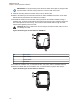
MN005720A01-AB Chapter 5: Motorcycle Radio Installation IMPORTANT: For proper seating of the antennas, deburr and scrape any foreign matter from both sides of the hole, being careful not to mar the finish of the shell. 9 Clean the mounting surface around the hole to remove dirt and wax. 10 Refer to the Motorcycle GPS Instruction Manual for further installation instruction for the GPS. GPS must be mounted before the metal liner is installed.
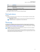
MN005720A01-AB Chapter 5: Motorcycle Radio Installation No. Description 1 Cable Clamp 2 Coaxial Cable 3 Attach to Antenna Connector on Radio 14 After routing the cable, allow enough of the cable to reach the radio antenna connector and cut off any excess length of the cable. 15 To install the connector, refer to the Antenna Installation Manual. 5.8 Installing the Antenna Procedure: 1 Connect the appropriate antenna connectors to the antenna receptacles on the radio.
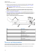
MN005720A01-AB Chapter 5: Motorcycle Radio Installation Figure 110: Cable Routing 2 3 1 4 10 12 13 11 9 14 5 8 6 7 No.
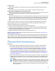
MN005720A01-AB Chapter 5: Motorcycle Radio Installation Speaker Cable Runs from the speaker to the accessory-cable connector inside the weather-resistant enclosure. Control Cable Runs from the rear of the control head to the front of the transceiver inside the enclosure. Ignition Sense (Red) Wire Portion of Accessory Cable Runs from the ignition sense fuse terminal of the fuse box to the rear area inside the enclosure. The lug for attaching the ignition sense wire is contained on the accessory cable.
MN005720A01-AB Chapter 5: Motorcycle Radio Installation 4 Install the 3-foot ground strap on one of the front shock mounts. Route it through the cablerouting hole and connect the other end to the motorcycle frame (see Figure 111: WeatherResistant Enclosure Installation on page 116). WARNING: DO NOT connect the ground strap directly to the negative battery post. 5 The diagram of the shock mount is shown loosely assembled.
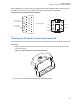
MN005720A01-AB Chapter 5: Motorcycle Radio Installation 5.11.1 Installing Cabling in the Enclosure Follow the procedure to position the cabling in the weather-resistant enclosure. Procedure: 1 Run the speaker, power, control-head, and ignition sense cables into the enclosure. 2 Lay the excess cable length between the radio mounting bosses in an S configuration as shown in Figure 112: Installing Cables on page 117. Do not coil any excess cable. Use the supplied tie wraps to bundle cable as shown.
MN005720A01-AB Chapter 5: Motorcycle Radio Installation No. Description 4 Control Head Power (Red) 5 Control Head Power Fuse 6 Control Head Ground (Black) 7 Ignition Sense (ACC) 8 Emergency Cable Shorting Plug 9 Headset Sporting Plug 10 Accessory Cable Headset Connector 11 Accessory Cable Emergency and External Alarm Connector 5.11.
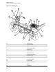
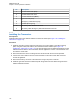
MN005720A01-AB Chapter 5: Motorcycle Radio Installation Figure 113: Installing the Transceiver 15 3 2 18 4 17 16 1 2 8 10 13 12 9 6 14 11 5 7 Table 16: Transceiver Installation Parts List No.
MN005720A01-AB Chapter 5: Motorcycle Radio Installation No. Description 4 Screw 5 Grommet 6 Screw 7 Lock catch 8 Radio mounting plate 9 Bottom housing 10 Ground shield plane 11 Top cover 12 Gasket 13 Hinge 14 Enclosure mounts 15 Transceiver 16 Screw 17 Trunnion 18 External tooth lock washer (8 used) 5.
MN005720A01-AB Chapter 5: Motorcycle Radio Installation When upgrading from a mobile radio, the existing headset cable HLN6890 requires these two pins to be swapped. The other motorcycle headset cable with this pin change is 3080010R07. Figure 114: Motorcycle Wiring Harness Rework 20 26 7 13 Remove from Pin 1 (VIP OUT 1) SPK + 1 2 SPK - GND 3 4 VIP OUT 1 AUX_PTT 5 6 AUX_MIC J2, BACK OF RADIO Insert into Pin 22 (Monitor) 21 14 8 1 (Female-Pins) 5.
MN005720A01-AB Chapter 5: Motorcycle Radio Installation Figure 116: Position the Sunshield 1 No. Description 1 Velcro Adhesive Backing 3 Slide the control head onto the trunnion while aligning the edge of the control head with the edge of the sunshield. Make sure the Velcro properly adheres to the control head. Figure 117: Slide the Control Head onto Trunnion 4 Position control head as desired and install screws.
MN005720A01-AB Chapter 5: Motorcycle Radio Installation Figure 118: Position Control Head as Desired 5.16 Horn/Lights Wiring Figure 119: Horn/Lights Wiring Diagram HORN/LIGHTS WIRING DIAGRAM CONNECT ACROSS HORN RING SWITCH OPTIONAL SECOND RELAY SWB+ SPST N.O. RELAY 12V COIL CONNECT ACROSS HEAD LAMP SWITCH SWB+ VIP OUT 2 12V COIL SPST N.O.
MN005720A01-AB Chapter 5: Motorcycle Radio Installation 5.17 Emergency Switch Wiring Figure 120: Emergency Switch Wiring Diagram NOTE 1 SPST NORMALLY CLOSED EMERGENCY SWITCH PIN 14 PIN 15 NOTE 1: REMOVE BLACK JUMPER WIRE INSIDE ACCESSORY CONNECTOR HOUSING. INSERT WIRES FROM EMERGENCY SWITCH 20 26 ACCESSORIES CONNECTOR 7 13 J2 IN DASH MOUNT J100 IN REMOTE MOUNT EMER GND 21 14 8 1 WARNING: Motorcycle products must have pins 1 and 2 connected together to allow the radio to power down.
MN005720A01-AB Finishing the Installation Chapter 6 Finishing the Installation This chapter provides the cable connection and dust cover installation procedure. 6.1 Cable Connection The topic provides the procedure for control heads cable connection. 6.1.1 Connecting the Cables for O2 Control Head Procedure: 1 Remove the control head from its mounting trunnion.
MN005720A01-AB Chapter 6: Finishing the Installation 2 Plug in the connector again. You hear a click sound. 3 Ensure that the location of the CAN connector is correct (such as J800L or J800R) on the transceiver interface. 4 Connect the plug from the speaker lead to the mating connector of either J2 or J626 (refer to the cabling diagram for more information). 6.1.3 Connecting the Cables for O5, E5 and O7 Control Heads Procedure: 1 Remove the control head from its mounting trunnion.
MN005720A01-AB Chapter 6: Finishing the Installation Figure 121: Dust Cover Installation Locations 1 2 3 4 5 2 6 1 6 8 1 2 1 7 4 9 3 10 5 6 7 7 11 No.
MN005720A01-AB Chapter 6: Finishing the Installation 6.3 Miscellaneous Information On the mid power radio, there are rubber port plugs which seals an opening that is used for future antenna connection. On the mid power radio, the port plug is at the bottom of the radio behind the control head or TIB. These plugs are critical to the sealing of the radio and should not be removed unless to replace it due to damage or to install the future antenna connector.
MN005720A01-AB Best Practices: Installation and Troubleshooting Chapter 7 Best Practices: Installation and Troubleshooting This chapter covers the Motorola Solutions recommended vehicle installation practices that can address or prevent many issues. • Radio circuit damage due to overvoltage condition. • Radio/Accessories "lock-up". • Radio/Accessories change state/lock-up when radio PTT is depressed. • Radio powers up in the FL 01/90 state (general communication error code).
MN005720A01-AB Chapter 7: Best Practices: Installation and Troubleshooting 7.2 Checking the Physical Installation of Radio Ground and Radio Accessory Wiring Dash and Remote Mount Configurations • Scrape away paint on the chassis at the place where you are making the ground connection, and try to keep the ground lead as short as possible.
MN005720A01-AB Chapter 7: Best Practices: Installation and Troubleshooting 7.4 Minimizing the Effect of Poorly Grounded Antennas For vehicles with high power radios that use glass mount antennas, keep the radio and antenna cable as far as possible from the radiating element of the antenna. If a sufficient distance is not maintained, the lack of a proper ground plane from the glass mount antenna may cause the radio transmit signal to interfere with itself and cause a reset.
MN005720A01-AB Appendix A: Replacement Parts Ordering Appendix A Replacement Parts Ordering Basic Ordering Information Some replacement parts, spare parts, and/or product information can be ordered directly from the Motorola Solutions local distribution organization or through Motorola Online. While parts may be assigned with a Motorola Solutions part number, this does not guarantee that they are available from Motorola Solutions Radio Products and Solutions Organization (RPSO).
MN005720A01-AB Appendix A: Replacement Parts Ordering Types of Orders Contact Information 8:30 AM to 5:00 PM (Eastern Standard Time) Fax Orders RPSO (United States and Canada) 1-800-622-6210 1-847-576-3023 (United States and Canada) USFGMD (Federal Government Orders) 1-800-526-8641 (For Parts and Equipment Purchase Orders) Product Customer Service RPSO (United States and Canada) 1-800-927-2744 NOTICE: The Motorola Solutions RPSO was formerly known as the Radio Products Services Division (RPSD) and/or t
MN005720A01-AB Appendix A: Replacement Parts Ordering A.2 Service Information – APAC This topic contains contact details to service centers in Asia and Pacific region. Technical Support Technical support is available to assist the dealer/distributor in resolving any malfunction which may be encountered. Initial contact should be by telephone wherever possible. When contacting Motorola Solutions Technical Support, be prepared to provide the product model number and the serial number.
MN005720A01-AB Appendix A: Replacement Parts Ordering Country Telephone Number Address Bangkok 10110 Contact: Nitas Vatanasupapon E-mail: Nitas@motorolasolutions.com India +91-9844218850 Motorola Solutions India Pvt. Ltd. C/o Communication Test Design India Private Limited, #4, 5 Maruthi Industrial Estate, Rajapalya, Hoodi Village, Bangalore - 560048, India Contact: K. Umamaheswari E-mail: umamaheshwari@motorolasolutions.com China +86-10-8473-5128 Motorola Solutions (China) Co. Ltd. No.
MN005720A01-AB Appendix A: Replacement Parts Ordering Country Telephone Number Australia +613-9847-7725 Address Motorola Solutions Australia Pty. Ltd. 10 Wesley Court, Tally Ho Business Park, East Burwood Victoria 3151, Australia. E-mail: servicecentre.au@motorolasolutions.com Piece Parts Some replacement parts, spare parts, and/or product information can be ordered directly.
MN005720A01-AB Glossary Glossary This glossary contains an alphabetical listing of terms and their definitions that are applicable to portable and mobile subscriber radio products. Analog Refers to a continuously variable signal or a circuit or device designed to handle such signals. band Frequencies allowed for a specific purpose. Customer Programming Software CPS-Software with a graphical user interface containing the feature set of an ASTRO radio. default A pre-defined set of parameters.
MN005720A01-AB Glossary Megahertz (MHz) One million cycles per second. Used especially as a radio-frequency unit. Megahertz One million cycles per second. Used especially as a radio-frequency unit. Microcontroller Unit MCU-Also written as µC. A microprocessor that contains RAM and ROM components, as well as communications and programming components and peripherals. PA Power amplifier. paging One-way communication that alerts the receiver to retrieve a message.
MN005720A01-AB Glossary Computer programs, procedures, rules, documentation, and data pertaining to the operation of a system. Time-out Timer TOT-A timer that limits the length of a transmission. transceiver Transmitter-receiver. A device that both transmits and receives analog or digital signals. Also abbreviated as XCVR. transmitter Electronic equipment that generates and amplifies an RF carrier signal, modulates the signal, and then radiates it into space. TX Transmit. UHF Ultra-High Frequency.