m MOTOTRBO™ Mobile Installation Guide XPR 2500 Display Mobile 68009622001-A -i
0
Foreword This manual is intended for use by experienced technicians familiar with similar types of equipment. Specifically, it contains installation information required for the XPR 2000 Series Mobile Radios. For information related to the service of the XPR 2000 Series Mobile Radios, refer to Related Publications on page v for the list of applicable manuals available separately.
Installation Requirements for Compliance with Radio Frequency (RF) Energy Exposure Safety Standards ATTENTION! This radio is intended for use in occupational/controlled conditions, where users have full knowledge of their exposure and can exercise control over their exposure to meet FCC limits. This radio device is NOT authorized for general population, consumer, or any other use. To ensure compliance to RF Energy Safety Standards: • Install only Motorola approved antennas and accessories.
Table of Contents iii Table of Contents Foreword ..........................................................................................................i Product Safety and RF Exposure Compliance .............................................................................................i Manual Revisions .........................................................................................................................................i Parts Ordering .............................................
iv 2.6 2.7 2.5.2 Antenna Installation Procedure....................................................................................... 2-11 2.5.3 Antenna Connection ....................................................................................................... 2-12 Overtightening the collar can damage the connector and the radio.Microphone Hang-Up Clip .. 2-13 2.6.1 Standard Hang-Up Clip...................................................................................................
List of Figures v List of Figures Figure 1-1 Figure 1-2 Front View of Dash Mount Trunnion for MOTOTRBO XPR 2000 Series mobiles ................ 1-2 Side View of Dash Mount with Low Profile Trunnion for MOTOTRBO XPR 2000 Series mobiles ...................................................................................................................... 1-2 Figure 1-3 Back View of the Mobile Radio .............................................................................................
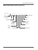
vi Mobile Radio Model Numbering Scheme Mobile Radio Model Numbering Scheme Model No.
Commercial Warranty vii Commercial Warranty Limited Warranty MOTOROLA COMMUNICATION PRODUCTS I. What This Warranty Covers and For How Long MOTOROLA INC.
viii Commercial Warranty II. General Provisions This warranty sets forth the full extent of MOTOROLA'S responsibilities regarding the Product. Repair, replacement or refund of the purchase price, at MOTOROLA's option, is the exclusive remedy. THIS WARRANTY IS GIVEN IN LIEU OF ALL OTHER EXPRESS WARRANTIES. IMPLIED WARRANTIES, INCLUDING WITHOUT LIMITATION, IMPLIED WARRANTIES OF MERCHANTABILITY AND FITNESS FOR A PARTICULAR PURPOSE, ARE LIMITED TO THE DURATION OF THIS LIMITED WARRANTY.
Commercial Warranty ix I. A Product which, due to illegal or unauthorized alteration of the software/firmware in the Product, does not function in accordance with MOTOROLA’s published specifications or the FCC type acceptance labeling in effect for the Product at the time the Product was initially distributed from MOTOROLA. J. Scratches or other cosmetic damage to Product surfaces that does not affect the operation of the Product. K. Normal and customary wear and tear. VI.
x Commercial Warranty Notes
Chapter 1 Introduction This manual covers the installation procedures for XPR 2000 Series Mobile Radios and accessories required to complete the radio system. The radio system consists of a control head, radio, antenna, microphone, speaker, cabling, and accessories. 1.1 Mobile Radio Description 1.1.1 Overview Model Description XPR 2500 Display model with 4 programmable buttons, dot-matrix LCD, and premium system software features available.
1-2 Introduction Mobile Radio Description 1.1.2 Dimensions Figure 1-1, Figure 1-2, Figure 1-3 and Figure 1-4 show the basic dimensions of the dash mount trunnion of the mobile radio. When installing the radio, make sure to plan the installation carefully and leave additional room in the rear of the radio for cabling and accessory connections; in the front of the radio for access, controls, and cabling; and to the sides of the radio so that you may access and install the trunnion wing screws. 8.2” 6.
Introduction Mobile Radio Description 1.1.3 1-3 Connections on the Back of the Radio Figure 1-3 shows the connections that are found on the back of the radio. For complete pin configuration of the rear accessory connector, see Figure 3-2 on page 3-2.
1-4 1.2 Introduction Standard Configurations Standard Configurations The XPR 2000 Series mobile can only be dash mounted. 1.2.1 Dash Mount Configuration In the dash mount configuration of the mobile radio, the control head is mounted on the front of the transceiver housing. Electrical connection between the two takes place within the radio via a flexible cable between the connectors on the front of the transceiver and at the back of the control head.
Chapter 2 Installation Details for Standard Configurations 2.1 Planning the Installation The mobile radio operates only in negative ground electrical systems. Before starting the radio installation, make sure that the ground polarity of the vehicle is correct. Accidentally reversing the polarity will not damage the radio, but will cause the cable fuses to blow. Planning is the key to fast, easy radio installation.
2-2 2.1.3 Installation Details for Standard Configurations Planning the Installation Wiring Diagrams Figure 2-2 shows the wiring diagrams for some of the possible configurations. Identify the configuration that you are installing, and use the diagram when planning the installation.
Installation Details for Standard Configurations Radio Mounting 2.2 2-3 Radio Mounting Caution Caution Caution DO NOT mount the radio on a plastic dashboard without first reinforcing the dashboard; the weight of the radio may crack or break the dashboard. DO NOT mount the radio on a flat or concave surface where the radio could be partially submersed in water. This is especially important if the cab area of the vehicle is cleaned by spraying with water.
2-4 2.2.1 Installation Details for Standard Configurations Radio Mounting Dash Mount with Trunnion 1. Select the location to mount your radio on the transmission hump (see Figure 2-4) or under the dash (see Figure 2-5). When mounting the trunnion on the transmission hump take care the transmission housing is not affected. 2. Using the trunnion mounting bracket as a template, mark the positions of the holes on the mounting surface.
Installation Details for Standard Configurations Radio Mounting 2-5 Trunnion Wing Screw Lock Washer Lock Washer Wing Screw Figure 2-5 Below Dash Trunnion Mounting
2-6 2.2.2 Installation Details for Standard Configurations Radio Mounting Locking Kit (Optional) 2.2.2.1 All Radios If an optional locking kit is used (shown in Figure 2-6), position the lock bottom housing on the trunnion before installing the radio mounting screws. Then slip the top lock housing on and remove the key. You can install the lock on either side of the radio. Lock Figure 2-6 Locking Kit (Optional) 2.2.3 DIN Mount 2.2.3.1 To install the frame into the dashboard 1.
Installation Details for Standard Configurations Radio Mounting 2-7 2.2.3.2 To Mount the radio in the frame 1. Provide the electrical connections for the radio (power, antenna, accessories). 2. Plug in all the connectors and push the radio firmly into the mounting frame until the two springs snap into place (shown in Figure 2-7).
2-8 Installation Details for Standard Configurations Power Cable 2.2.3.3 To Remove the radio from the frame 1. Push the two demounting tools through the openings in the frame until the two springs release the radio. 2. Slide out the radio. NOTE: The fixing tabs should be checked for tightness each time the radio is removed. The tabs are easily tightened by twisting a large flat-head screwdriver in the slot behind the tabs. NOTE: The frame is not designed for regular mounting and demounting. 2.
CAUTION CH SPEAKER MICROPHONE SEE NOTE ON/ACC 3A OR 4A FUSE RADIO POWER CABLE (RED/BATTERY HOT) RADIO IGNITION CABLE (thin RED) VEHICLE IGNITION SWITCH 15A OR 20A FUSE GROMMET (-) VEHICLE BATTERY (+) PART OF VEHICLE WIRING VEHICLE BATTERY COMPARTMENT Figure 2-8 Cabling Interconnect Diagram for Dash Mount If the radio’s IGNITION line is wired to the car’s ignition switch, the radio will only function when the car’s ignition switch is turned ON.
2-10 2.4 Installation Details for Standard Configurations Ignition Sense Cable Ignition Sense Cable Motorola supplies an ignition sense cable and recommends that it be used with every mobile installation. The ignition sense cable allows the radio to be turned on and off with the vehicle ignition switch, and allows the radio to “remember” the state of the radio on/off switch, even if it is changed while the vehicle is off.
Installation Details for Standard Configurations Antenna Installation 2-11 NOTE: Any two metal pieces rubbing against each other (such as seat springs, shift levers, trunk and hood lids, exhaust pipes, etc.) in close proximity to the antenna can cause severe receiver interference. 2.5.2 Antenna Installation Procedure 1. Mount the antenna according to the instructions provided with the antenna kit. Run the coaxial cable to the radio mounting location.
2-12 2.5.3 Installation Details for Standard Configurations Antenna Installation Antenna Connection To ensure a secure connection of an antenna cable's mini-UHF plug to a radio's mini-UHF jack, their interlocking features must be properly engaged. If they are not properly engaged, the system will loosen. NOTE: Applying excessive force with a tool can cause damage to the antenna or the connector (e.g.
Installation Details for Standard Configurations Overtightening the collar can damage the connector and the radio.Mi- 2.6 Overtightening the collar can damage the connector and the radio.Microphone 2.6.1 Standard Hang-Up Clip Clip Hang-Up The hang-up clip must be within reach of the operator(s). Measure this distance before actually mounting the bracket. Since the bracket has a positive-detent action, the microphone can be mounted in any position. The microphone hang-up clip must be grounded.
2-14 Installation Details for Standard Configurations Notes
Chapter 3 Options and Accessories Installation 3.1 Accessory Installation The accessories must be installed through the rear accessory connector that is located on the rear of the radio, adjacent to the power connector. Most of the Motorola-approved accessories are supplied with female terminals crimped to a 20-gauge wire specifically designed to fit the plug of the rear accessory connector. Insert the female terminal into the accessory connector assembly in the appropriate locations.
3-2 Options and Accessories Installation Accessory Installation Table 3-1 Rear Accessory Connector Pin Functions 3 4 11 Rx Audio Receive Live Audio2 12 GPIO_7 5V Level GPIO GPI_1 (PTT) VIP_1 (Ext Alarm) Speaker – (3.
Options and Accessories Installation Accessory Installation Emergency Pushbutton or Footswitch Installation Mount the emergency pushbutton (Motorola part number RLN4857_) or the footswitch (Motorola part number RLN4836AR_) using the hardware that comes with the kit. Press the terminal into the accessory connector housing. Connect the emergency switch wires to pins 9 and 7 (see Figure 3-3). Route the finished cable from the switch location to the control head location.
3-4 Horn and Lights (External Alarm) Relay Allows the user to be alerted to an incoming call when away from the vehicle. The vehicle's horn or lights or both are used depending on which option is connected to the accessory port. When the radio receives a call alert or emergency alarm/call, there is a delay before activating the horn and/or lights. The delay is programmable using the Horn & Lights Delay Time feature in the CPS.
Options and Accessories Installation Accessory Installation 3-5 3.1.3 External Speaker Caution DO NOT ground the radio's speaker leads. This system has a floating speaker output (dc voltage on both leads); damage to the audio circuit will result if either lead is grounded or if they are shorted together. The external speaker kit includes a trunnion bracket that allows the speaker to be mounted in a variety of ways.
3-6 Options and Accessories Installation Notes
Chapter 4 Best Practices: Installation & Troubleshooting In this section are Motorola recommended vehicle installation practices that can address or prevent many issues, including: • Radio circuit damage due to over voltage condition • Radio/Accessories "lock up" • Radio/Accessories change state/lock-up when radio PTT is depressed • Radio intermittently resets • Alternator whine present when transmitting with engine running • Radio/Accessories turn themselves on/off 4.
4-2 4.2 Best Practices: Installation & Troubleshooting Check Physical Installation of Radio Ground and Radio Accessory Wiring • Take care to scrape away paint on the chassis at the place where the ground connection is to be made, and try to keep the ground lead as short as possible. • Verify that the A+ lead (red) is connected directly to the positive terminal of the battery and the ground lead (black) is connected to the vehicle’s chassis using as short of a length of wire as is practical.
Best Practices: Installation & Troubleshooting 4.4 4-3 Jump-Start the Vehicle Do not jump-start vehicle with radio power or ignition sense cables connected. Damage to the radio and/or accessories may result. Caution The state of your radio prior to needing a jump-start may be unknown, and the radio may attempt to return to its last state (radio ON), when doing a jump-start. Therefore, Motorola recommends the following steps be taken before jump-starting any vehicle containing a radio. 1.
4-4 Best Practices: Installation & Troubleshooting Notes
Appendix A A.1 Replacement Parts Ordering Basic Ordering Information When ordering replacement parts or equipment information, the complete identification number should be included. This applies to all components, kits, and chassis. If the component part number is not known, the order should include the number of the chassis or kit of which it is a part, and sufficient description of the desired component to identify it.
-2 A.5 Fax Orders Fax Orders Radio Products and Solutions Organization* (United States and Canada) 1-800-622-6210 1-847-576-3023 (International) USFGMD (Federal Government Orders) 1-800-526-8641 (For Parts and Equipment Purchase Orders) A.6 Parts Identification Radio Products and Solutions Organization* (United States and Canada) 1-800-422-4210 A.
Appendix B B.1 Motorola Service Centers Servicing Information If a unit requires further complete testing, knowledge and/or details of component level troubleshooting or service than is customarily performed at the basic level, please send the radio to a Motorola Service Center as listed below. B.2 Motorola Service Center 1220 Don Haskins Drive Suite A El Paso, TX 79936 Tel: 915-872-8200 B.
-2 Motorola Canadian Technical Logistics Center Notes
Index Index A accessories installing dash mount ........................................................3-1 pin configuration .................................................3-2 pin functions .......................................................3-2 antenna cable, see Cables, antenna connection ...........................................................2-12 diagrams ..............................................................2-12 installing .............................................................
Index-2 W wiring diagrams .........................................................