
Service manual


June, 2005 6880309N62-C
3-2 Controller Theory of Operation: Controller
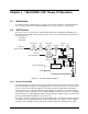
3.1.1.1 Memory Usage
Radio operation is controlled by software that is stored in external Flash ROM memory (U404).
Radio parameters and customer specific information is stored in external EEPROM (U402). The
operating status of the radio is maintained in RAM located within the microprocessor. When the radio
is turned off, the operating status of the radio is written to EEPROM before operating voltage is
removed from the microprocessor. See section “3.1.1.7 Microprocessor Power-Up, Power-Down and
Reset Routine” on page 3-3 for a discussion of the power-down routine.
Parallel communication with U403 and U404 is via:
• address lines A(0)-A(16), from U401 port F ADDR0-ADDR13 and port G XA14-XA16
• data lines D(0)-D(7), from U401 port C DATA0-DATA7
• chip-select for U403, from PH6 (U401 pin 41)
• chip-enable for U404, from PH7 (U401 pin 38)
• output enable for U404, from PA7 (U401 pin 86)
• write-enable for both U403 and U404, from PG7_R/W (U401 pin 4)
Serial communication with U402 is via:
• the SPI bus (see section “3.1.1.3 Serial Bus Control of Circuit Blocks” on page 3-2)
• chip-select for U402, from PD6 (U401 pin 3)
3.1.1.2 Control and Indicator Interface
Ports PI3 and PI4 are outputs which control the top-mounted LED indicator. When PI3 is high, the
indicator is red. When PI4 is high, the indicator is green. When both are high, the indicator is amber.
When both are low, the indicator is off.
Pressing the side-mounted PTT button (S441) provides a low to port PJ0 (U401 pin 71), which
indicates PTT is asserted. Side-mounted option buttons 1 and 2 (S442 and S443) are connected to
Ports PJ6 (pin 77) and PJ7 (pin 78), respectively.
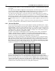
3.1.1.3 Serial Bus Control of Circuit Blocks
The microprocessor communicates with other circuit blocks via a SPI (serial peripheral interface) bus
using ports PD2 (data into uP), PD3 (data out of uP) and PD4 (clock). The signal names and
microprocessor ports are defined in Table 3-2.
These signals are routed to:
• the audio filter IC (U451) to control internal functions such as gain change between 25 kHz and
12.5 kHz channels, transmit or receive mode, volume adjustment, etc.
• the synthesizer IC U201 to load receive and transmit channel frequencies
• option board connector J460-1 for internal option configuration and control
• serial EEPROM U402 (both SPI_DATA_IN and SPI_DATA_OUT are used).
Table 3-2. SPI Bus Signal Definitions
Signal Name Microprocessor Port Microprocessor Pin
SPI-DATA_IN PD2-MISO U401 Pin 99
SPI_DATA_OUT PD3-MOSI U401 pin 100
SPI_CLK PD4-SCK U401 pin 1