
Service manual


Chapter 5 146-174 MHz VHF Theory Of Operation
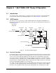
5.1 Introduction
This chapter provides a detailed theory of operation for the radio components. Schematic diagrams
for the circuits described in the following paragraphs are located in Chapter 7 of this manual.
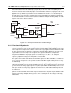
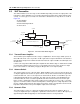
5.2 VHF Receiver
The VHF receiver covers the range of 146-174 MHz and provides switchable IF bandwidth for use
with 12.5 kHz or 20/25 kHz channel spacing systems. The receiver is divided into two major blocks as
shown in Figure 5-1.
•Front End
• Back End
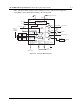
Figure 5-1. VHF Receiver Block Diagram
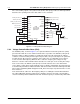
5.2.1 Receiver Front-End
Incoming RF signals from the antenna are first routed through the harmonic filter and antenna switch,
part of the transmitter circuitry, before being applied to the receiver front end. The receiver front end
consists of a preselector filter, RF amplifier, an interstage filter, and a double-balanced first mixer.
The preselector filter is a fixed-tuned 4-pole design using discrete elements (L1-L4 and C1-C9) in a
series/shunt resonator configuration. It has a 3 dB bandwidth of 44 MHz, an insertion loss of 2 dB and
image attenuation of 40 dB at 235 MHz, with increasing attenuation at higher frequencies. Diode CR1
protects the RF amplifier by limiting excessive RF levels.
The output of the filter is matched to the base of RF amplifier Q21, which provides 18 dB of gain and
a noise figure of 2 dB. Operating voltage is obtained from the 5R source, which is turned off during
transmit to reduce dissipation in Q21. Current mirror Q22 maintains the operating current of Q21
Demodulator
Crystal
Filter
1st Mixer
RF
Amp
IF
Amp
Preselector
Filter
Interstage
Filter
Recovered Audio
RSSI
RX from
Antenna Switch
Inj Filter
First LO
from Synthesizer
Ceramic
Resonator
Cer Fltr
Switching
4E
6E
6G
BW_SEL