Mag One™ by Motorola Radio Series Basic Service Manual 6816101H01-A
Computer Software Copyrights The Motorola products described in this manual may include copyrighted Motorola computer programs stored in semiconductor memories or other media. Laws in the United States and other countries preserve for Motorola certain exclusive rights for copyrighted computer programs, including, but not limited to, the exclusive right to copy or reproduce in any form, the copyrighted computer program.
i DOCUMENT HISTORY The following major changes have been implemented in this manual since the previous edition: Edition 6816101H01-A Description Initial edition Date Mar.
ii Notes
iii Safety Information Product Safety and RF Energy Exposure Booklet for Portable Two-Way Radios The information provided in this document supersedes the general safety information contained in user guides published prior to February 2002.
iv Exposure awareness can be facilitated by the use of a product label directing users to specific user awareness information. Your Motorola two-way radio has a RF exposure product label. Also, your Motorola user manual, or separate safety booklet includes information and operating instructions required to control your RF exposure and to satisfy compliance requirements.
v Operating Instructions • Transmit no more than the rated duty factor of 50% of the time. To transmit (talk), push the PushTo-Talk (PTT) button. To receive calls, release the PTT button. Transmitting 50% of the time, or less, is important because this radio generates measurable RF energy exposure only when transmitting (in terms of measuring for standards compliance).
vi Persons with pacemakers should: • ALWAYS keep the radio more than 6 inches (15 centimeters) from their pacemaker when the radio is turned ON. • Not carry the radio in the breast pocket. • Use the ear opposite the pacemaker to minimize the potential for interference. • Turn the radio OFF immediately if there is any reason to suspect that interference is taking place. Hearing Aids Some digital wireless radios may interfere with some hearing aids.
vii Operational Cautions Antennas Do not use any portable radio that has a damaged antenna. If a damaged antenna comes into contact with your skin, a minor burn can result. Batteries All batteries can cause property damage and/or bodily injury, such as burns, if a conductive material such as jewelry, keys, or beaded chains touches exposed terminals. The conductive material may complete an electrical circuit (short circuit) and become quite hot.
viii A modification changes the unit's hardware from its original design configuration. Modifications can only be made by the original product manufacturer. • Do not replace or change accessories in a hazardous atmosphere. Contact sparking may occur while installing or removing accessories and cause an explosion or fire. • Turn the radio off before removing or installing a battery or accessory. • Do not disassemble an intrinsically safe product in any way that exposes the internal circuits of the unit.
Table of Contents Document History ................................................................................................. .i Safety Information ... ............................................................................................ iii Section 1 1.0 2.0 3.0 4.0 Scope of Manual ... .................................................................................................. .1-1 Warranty and Service Support... ........................................................................
2.1 Tuning Frequency ... ....................................................................................... ...3-2 2.2 Preparation Before Tuning (refer to Figure 3-1) ... ............................................. .3-2 2.3 Transmitter Tuning ... ....................................................................................... ...3-3 2.4 Receiver Tuning ... ............................................................................................. .3-6 Section 4 1.0 2.0 3.0 4.
Scope of Manual 1-1 Section 1 INTRODUCTION 1.0 Scope of Manual This manual is intended for use by service technicians familiar with similar types of equipment. It contains service information required for the equipment described and is current as of the printing date. Changes which occur after the printing date may be incorporated by a complete Manual revision or alternatively as additions.
1-2 2.2 Warranty and Service Support After Warranty Period NOTE For service technicians in the Latin America Countries Region After Warranty Period claims in the Latin America Countries region are handled through the Motorola Authorized Service Provider (SAM) Network. To find the nearest SAM, please go to Motorola Resource Center in Motorola Online at https://businessonline.motorola.com/ . After the Warranty period, Motorola continues to support its products in two ways. 2.3 1.
Radio Model Information 3.0 1-3 Radio Model Information The model number and serial number are located on a label attached to the back of your radio. You can determine the RF output power, frequency band, protocols, and physical packages. The example below shows one portable radio model number and its specific characteristics.
1-4 Radio Features 4.0 Radio Features The following are features your radio has.
2-1 Section 2 MAINTENANCE 1.0 Introduction This chapter provides details about the following: 2.0 • Preventive Maintenance • Safe Handling of CMOS and LDMOS Devices • General Repair Procedures and Techniques • Disassembling and Reassembling the Radio Preventive Maintenance Periodic visual inspection and cleaning is recommended. 2.1 Inspection Check that the external surfaces of the radio are clean, and that all external controls and switches are functional.
2-2 Safe Handling of CMOS and LDMOS Devices Cleaning Internal Circuit Boards and Components Isopropyl alcohol (70%) may be applied with a stiff, non-metallic, short-bristled brush to dislodge embedded or caked materials located in hard-to-reach areas. The brush stroke should direct the dislodged material out and away from the inside of the radio. Make sure that controls or tunable components are not soaked with alcohol.
Repair Procedures and Techniques — General 4.0 2-3 Repair Procedures and Techniques — General Parts Replacement and Substitution When damaged parts are replaced, identical parts should be used. If the identical replacement part is not locally available, check the parts list for the proper Motorola part number and order the part from the nearest Motorola Communications parts center listed in the Piece Parts section of this manual.
Disassembling and Reassembling the Radio — General 2-4 5.0 • To replace a chip component using a soldering iron, select the appropriate micro-tipped soldering iron and apply fresh solder to one of the solder pads. Using a pair of tweezers, position the new chip component in place while heating the fresh solder. Once solder wicks onto the new component, remove the heat from the solder. Heat the remaining pad with the soldering iron and apply solder until it wicks to the component.
Radio Disassembly — Detailed 2-5 6.0 Radio Disassembly — Detailed 6.1 Front Cover from Chassis Disassembly 1. Turn off the radio. 2. Unlatch the battery latch at the bottom of the radio (see “Figure 2-1”). Remove the battery by gently lifting the hilt of the battery, nearest to the battery latch, away from the housing. 3 2a 2b 2a Figure 2-1 3. Slide the battery downwards to remove the battery. 4. Remove the antenna by unscrewing it (see “Figure 2-2”). 5.
Radio Disassembly — Detailed 2-6 6. Insert the Chassis Opener at the bottom of the radio, between the chassis and housing (see “Figure 2-2”). Lift the chassis gently. Be careful not to damage the housing or the O-ring underneath. 7. Lift rear chassis away from the front cover. Be careful not to damage the speaker wire underneath. Speaker Wire Figure 2-3 8. Slide the rear chassis downwards, and away from the front cover. 9.
Radio Disassembly — Detailed 2-7 12. Slide the battery latch shaft out from the latch. Figure 2-5 NOTE Proceed to perform steps 13, 14, and 15 only if there is a need to replace the speaker, speaker bracket or speaker felt. 13. Unscrew the speaker bracket from the housing (see “Figure 2-6”). 14. Remove the speaker from on top of the speaker felt with a flat head screwdriver. 15. Remove the speaker felt from the grille area.
Radio Reassembly — Detailed 2-8 6.2 PC Board Disassembly 1. Remove the audio jack seal. 2. Remove the 10 screws which hold the PC board to the diecast. 3. Next, remove the 2 nuts on the On/Off Volume and Channel knobs shafts with the Crab Eye Nut Opener. 4. The PC board can now be removed from the rear diecast. 5. The completely disassembly PC board is shown in “Figure 2-7”.
Radio Reassembly — Detailed 7.2 2-9 Chassis and Front Cover Reassembly NOTE Proceed to perform steps 1, 2, 3 and 4 only if there is a need to replace the speaker, speaker bracket or speaker felt. 1. Place the speaker felt onto the grille area (see “Figure 2-8”) . 2. Place the speaker on top of the felt. Figure 2-8 3. Stick the speaker poron pad onto the back of speaker magnet. 4. Place the speaker bracket and screw the bracket to the housing.
Radio Reassembly — Detailed 2-10 Figure 2-10 7. With the battery latch placed on the housing, push the shaft in the housing slot to the left (see “Figure 2-11”). Figure 2-11 8. Place the small latch pad onto the right slot space (see “Figure 2-11”).
Radio Reassembly — Detailed 9. 2-11 Connect the internal speaker connector to the PC board (“see “Figure 2-12”). Speaker Connector Figure 2-12 10. Place the diecast into the front housing (see “Figure 2-13”). Figure 2-13 11. Snap the front housing cover firmly into place on the rear diecast . 12. Attach the battery. 13. Attach the On/Off Volume Knob, Channel Knob and Antenna.
2-12 Mechanical View and Parts List 8.0 Mechanical View and Parts List 8.
Mechanical View and Parts List 2-13 Table 2-1 Parts List Reference No Part No 6 PMDN4007_R PTT Rubber 1 7 PMDN4010_R PTT Bezel 1 8 PMDN4011_R Speaker & Cable (non-EPP) 1 PMDN4067_R Speaker & Cable (EPP) 1 PMDN4012_R Speaker Bracket 1 Speaker Bracket Screw 1 9 10 Part Name Qty 11 PMDN4013_R Speaker Poron Pad 1 12 PMDN4046_R Speaker Felt 1 13 PMDN4014_R Volume Knob 1 Volume Knob D-Clip (D: 6.0) 1 Channel Knob 1 Channel Knob D-Clip (D: 3.
2-14 Mechanical View and Parts List Table 2-1 Parts List Reference No 27 Part No Part Name † Qty PMDD4000_R 136 - 150 MHz 5W PC Board (EPP) 1 PMDD4001_R* 150 - 174 MHz 5W PC Board (non-EPP) 1 PMDD4005_R 150 - 174 MHz 5W PC Board (EPP) 1 PMDD4006_R* 148 - 174 MHz 5W PC Board (non-EPP) 1 † 148 - 174 MHz 5W PC Board (EPP) 1 PMDE4000_R † 403 - 425 MHz 5W PC Board (EPP) 1 PMDE4001_R* 450 - 470 MHz 4W PC Board (non-EPP) 1 PMDE4005_R 450 - 470 MHz 4W PC Board (EPP) 1 PMDN4068_R Rad
Mechanical View and Parts List 2-15 Table 2-1 Parts List Reference No Part No 48 PMAD4050_R Mag One™ 136-150MHz Antenna 1 PMAD4051_R Mag One™ 150-174MHz Antenna 1 PMAE4019_R Mag One™ 403-425MHz Antenna 1 PMAE4020_R Mag One™ 450-470MHz Antenna 1 PMAE4028_R Mag One™ 490-512MHz Antenna 1 Mag One™ Spring Belt Clip 1 Mag One™ NiMH Battery 1200mAH 1 Mag One™ NiMH Battery (Chinese Label) 1 PCB-Chassis Tape for PMUD2085A_, PMUD2086A_, PMUD2087A_, PMUD2171A_, PMUE2384A_, PMUE2385A_, PMUE23
2-16 9.0 Service Aids Service Aids Table 2-2 lists service aids recommended for working on the Mag One™ by Motorola Radios. While all of these items are available from Motorola, most are standard shop equipment items, and any equivalent item capable of the same performance may be substituted for the item listed. Table 2-2 Service Aids Motorola Part No. Description Application PMDN4038_R Chassis Opener To disassemble the radio PMDN4039_R Crab Eye Nut Opener To fasten or remove crab-eye nut.
Test Equipment 10.0 2-17 Test Equipment Table 2-3 lists test equipment required to service the Mag One™ by Motorola Radios and other twoway radios. Table 2-3 Recommended Test Equipment Motorola Part No. Description Characteristics Application R2600 Communication Analyzer Frequency/deviation meter and signal generator for wide-range troubleshooting and alignment R1038 Handheld Multimeter AC/DC Voltage and current measurements S1339A/220 RF Millivolt Meter 220V 100mv to 3VRF 100kHz to 1.
2-18 12.0 Cloning Cable (PMDN4060_R )otes 2.5pi e 2.5pie Figure 2-16 Cloning Cable Schematic 13.0 Test Box (PMDN4040_R) 1M ohm 1 0uF 8 ohm AUDIO 1 2 4ohm 1 Mohm AUDIO 1 S W1 1 0uF 3. 5pe SW2 8 ohm or 24 ohm T X AU DI O 2 . 2Kohm 2 .
3-1 Section 3 RADIO TUNING 1.0 Introduction This chapter provides an overview of the hardware tuning for this Mag One™ Series radio. There is no software tuning required. In order to perform the manual tuning procedures, the radio needs to be disassembled to the PC Board. Following are the parameters that can be tuned:1. 2. 3. Transmitter Tuning a. High Power Tuning b. Low Power Tuning c. Frequency Tuning d. Modulation Balancing e. Maximum Modulation f. Subtone Modulation Receiver Tuning a.
3-2 Hardware Tuning Setup and Procedure 2.0 Hardware Tuning Setup and Procedure 2.1 Tuning Frequency Table 3-1 Band Frequencies Used for Tuning. Tuning Parameter Frequency (MHz) PLL Synthesizer 149.975 Transmitter 136.025 Receiver 136.025 Modulation Balance 136.025 (N band) Sub-Tone Modulation 149.975 (S band) Maximum Modulation 149.975 (S band) PLL Synthesizer 173.975 Transmitter 150.025 Receiver 150.025 Modulation Balance 150.025 (N band) Sub-Tone Modulation 173.
Hardware Tuning Setup and Procedure 3. 3-3 Connect the radio to the test equipment. Ground Contact Finger TEST BOX Antenna Port Acc Jack 8 ohm 24 ohm BNC BNC Radio Tx Rx N Type TEST EQUIPMENT BNC Input Hi BNC Output Lo Figure 3-1 Radio Tuning Setup NOTE On the Test Box, select 8 ohm resistance when using with PMUD2085A_, PMUE2384A_. For all other kits, please select 24 ohm resistance. NOTE The radio may need to be disassembled to the PC board level to access certain tuning ports.
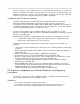
3-4 Hardware Tuning Setup and Procedure 4. Using the ceramic tool, adjust R425 to tune high power (refer to Figure 3-2). R425 R426 R216 FL701 R215 Figure 3-2 Tuning Ports 2.3.2 2.3.3 2.3.4 Low Power 1. Connect the radio to power meter. 2. Set the radio to the appropriate tuning frequency (refer to Table 3-1). 3. Key up the radio. 4. Using the ceramic tool, adjust R426 to tune low power (refer to Figure 3-2). Frequency Tuning 1.
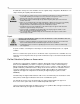
Hardware Tuning Setup and Procedure 3-5 R159 TP1 R174 R172 Figure 3-3 Top Side of PCB 5. Using the ceramic tool, adjust R174 (refer to Figure 3-3) to modulation balance as per Figure 3-4. Figure 3-4 Improperly tuned modulation balance can cause errors in Tx sub-tone modulation.
3-6 2.3.5 Hardware Tuning Setup and Procedure Maximum Modulation 1. Set the radio to the appropriate tuning frequency (refer to Table 3-1). 2. On the test equipment, set the following configurations: Audio bandwidth: 0.25Hz to 15,000Hz De-emphasis: Off FM: Peak negative 2.3.6 3. Using the Audio Analyzer, input a 1kHz tone + 67Hz subtone, 120mV to the radio through the test box. 4. Key up the radio. 5. Using the ceramic tool, adjust R159 to tune maximum modulation between 2.4 ± 0.
Hardware Tuning Setup and Procedure 5. 2.4.3 3-7 Then adjust R216 counterclockwise at the point where the Audio Frequency signal appears. PLL Synthesizer Tuning Rx PLL Frequency Tuning 1. Set the radio to the appropriate tuning frequency (refer Table 3-1). 2. Detect output voltage at test point TP1 (refer to Figure 3-3). 3. Using the ceramic tool, adjust C710 to tune the voltage to 5.0V +/-0.1V(refer to Figure 3-5).
3-8 Notes
Introduction 4-1 Section 4 RADIO PROGRAMMING 1.0 Introduction The radios can be programmed using the Customer Programming Software (CPS). 2.0 Programming Your Radio 2.1 Overview of the Programming Process To prepare properly programmed radios for your customers, you should 2.2 1. program your radio with all the necessary parameters, as required by your customers, and then 2. clone these parameters over to all your customer‟s radios.
4-2 2.5.2 2.5.3 2.6 CPS Programming Setting Up the Slave Radio 1. Turn off the radio. 2. Press and hold Programmable Button 1(the top programmable button) and turn on the radio. Keep pressing Programmable Button 1 until the beep is heard three times. 3. Release Programmable Button 1. Notice that the LED changes to GREEN. Radio to Radio Cloning Procedures 1. Connect the cloning cable to both the Master and Slave radio. 2. Press and release Programmable Button 1 of the Slave radio. 3.
Factory Reset 4-3 Refer to the diagram below for the programming setup. Radio Programming Cable PMDN4043_R Comm Port Figure 4-1 CPS Programming Setup 3.1 3.2 4.0 To Read Radio Data to a PC 1. Turn off the radio. 2. Connect the programming cable to the radio. 3. Press and hold Programmable Button 1 (top side button on the radio), then turn on the radio. 4. The radio beeps once. Immediately release Programmable Button 1. The radio‟s LED illuminates in orange. 5.
4-4 Factory Reset Notes
Antennas 5-1 Section 5 ACCESSORIES 1.0 2.0 3.0 4.0 5.
5-2 6.0 7.0 8.
VHF Band 1 Information (136-150 MHz) 6-1 Section 6 MODEL CHART AND TEST SPECIFICATION NOTE For specific models and options configuration, please refer to the Price Pages available on Motorola Online at https://businessonline.motorola.com/ . 1.0 VHF Band 1 Information (136-150 MHz) A8 136-150 MHz VHF Model Description LAH84JDC8AA4AN A8 136-150 MHz, 5W, 12.
6-2 2.0 Specifications Specifications Transmitter General VHF VHF Frequency: 136-150MHz Channel Capacity: 16 Power Supply: 7.5 Volts ±20% Dimensions with Standard High Capacity NiMH Battery: 118mm x 56mm x 37mm Weight with Standard High Capacity NiMH Battery: 350g Sealing: Passes rain testing per IPX4 (EN60529=1991) Shock and Vibration: Meets MIL STD 810C, D E and F Dust: Humidity: Channel Spacing 12.5/25 kHz Freq. Stability (-30°C to +60°C) 0.
VHF Band 2 Information (150 - 174 MHz) 3.0 6-3 VHF Band 2 Information (150 - 174 MHz) A8 150-174 MHz VHF Model Description LAH84KDC8AA4AN A8 150-174 MHz, 5W, 12.
6-4 4.0 Specifications Specifications Transmitter General VHF VHF Frequency: 150-174 MHz Channel Capacity: 16 Power Supply: 7.5 Volts ±20% Dimensions with Standard High Capacity NiMH Battery: 118mm x 56mm x 37mm Weight with Standard High Capacity NiMH Battery: 350g Sealing: Passes rain testing per IPX4 (EN60529=1991) Shock and Vibration: Meets MIL STD 810C, D E and F Dust: Humidity: Channel Spacing 12.5/25 kHz Freq. Stability (-30°C to +60°C) 0.
UHF Band 1 Information (403-425MHz) 5.0 6-5 UHF Band 1 Information (403-425MHz) A8 403-425 MHz UHF Model Description LAH84QCC8AA4AN A8 403-425 MHz, 4W, 12.
6-6 6.0 Specifications Specifications Transmitter UHF General UHF Channel Spacing 12.5/25 kHz Frequency: 403-425MHz Freq. Stability (-30°C to +60°C) 0.00025% Channel Capacity: 16 Spurs/Harmonics: -27 dBm Power Supply: 7.5 Volts ±20% +1, -3 dB Dimensions with Standard High Capacity NiMH Battery: 107mm x 58mm x 37mm Audio Response: (from 6 dB/oct. PreEmphasis, 300 to 3000Hz) 350g Audio Distortion: @ 1000 Hz, 60% Rated Max. Dev.
UHF Band 2 Information (450 - 470MHz) 7.0 6-7 UHF Band 2 Information (450 - 470MHz) A8 450-470 MHz UHF Model Description LAH84RCC8AA4AN A8 450-470 MHz, 4W, 12.5/25K-16CH Option STDCHG0027AE Standard Mid-Rate Charger 120V US Plug 60Hz Option Q665AG Mid-Rate Charger 230V EURO Plug 50Hz Option Q312BD Mid-Rate Charger Base Only - Argentina Option Q91AB Mid-Rate Charger 240V UK Plug 50Hz Option H951FF Delete Standard Charger Item Description X X X X X X PMUE2384AAL A8 450-470 MHz 4W 12.
6-8 8.0 Specifications Specifications Transmitter UHF General UHF Channel Spacing 12.5/25 kHz Frequency: 450-470 MHz Freq. Stability (-30°C to +60°C) 0.00025% Channel Capacity: 16 Spurs/Harmonics: -27 dBm Power Supply: 7.5 Volts ±20% +1, -3 dB Dimensions with Standard High Capacity NiMH Battery: 107mm x 58mm x 37mm Audio Response: (from 6 dB/oct. PreEmphasis, 300 to 3000Hz) 350g Audio Distortion: @ 1000 Hz, 60% Rated Max. Dev.
UHF Band 4 Information (490 - 512 MHz) 9.0 6-9 UHF Band 4 Information (490 - 512 MHz) A8 490-512 MHz UHF Model Description LAH84TCC8AA4AN A8 490-512 MHz, 4W, 12.5/25K-16CH Option STDCHG0027AE Standard Mid-Rate Charger 120V US Plug 60Hz Option Q665AG Mid-Rate Charger 230V EURO Plug 50Hz Option Q312BD Mid-Rate Charger Base Only - Argentina Option Q91AB Mid-Rate Charger 240V UK Plug 50Hz Option H951FF Delete Standard Charger Item Description X X X X X X PMUE2771AAL A8 490-512 MHz 4W 12.
6-10 10.0 Specifications Specifications Transmitter UHF General UHF Channel Spacing 12.5/25 kHz Frequency: 490-512 MHz Freq. Stability (-30°C to +60°C) 0.00025% Channel Capacity: 16 Spurs/Harmonics: -27 dBm Power Supply: 7.5 Volts ±20% +1, -3 dB Dimensions with Standard High Capacity NiMH Battery: 107mm x 58mm x 37mm Audio Response: (from 6 dB/oct. PreEmphasis, 300 to 3000Hz) 350g Audio Distortion: @ 1000 Hz, 60% Rated Max. Dev.
G-1 GLOSSARY OF TERMS Term Definition Busy Channel Lockout (BCLO) If BCLO is activated, the radio will check for channel activity before transmitting. If activity is detected, transmission is prohibited. For carrier squelch mode, radio will not transmit, if it is receiving carrier. For coded squelch mode, it will not transmit, if it is receiving carrier with different PL/DPL code.
G-2 Term Definition ROM Read Only Memory. Scan List The Scan List determines which channels the radio scans, when operating in the Scan Mode, on the current channel. Scan List Member The Scan List allows you to select the grouping of channels that make up the current Scan List Member channels. This grouping of Scan List Member channels can then be scanned for transmission activity - one at a time, when the radio is in Scan Mode. A Scan List can have a maximum of 16 Scan List Members.
©2007 by Motorola, Inc. All rights reserved. Mag One by Motorola is registered in the U.S. Patent and Trademark Office. All other product or service names are the property of their respective owners. Motorola, Inc. 8000 West Sunrise Boulevard Plantation, FL 33322 U.S.A.