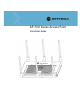
AP-7131 Series Access Point INSTALLATION Installation Guide
Contents 1.0 Introduction . . . . . . . . . . . . . . . . . . . . . . . . . . . . . . . . . . . . . . . . . 1 1.1 Document Conventions . . . . . . . . . . . . . . . . . . . . . . . . . . . . . . . . . . 2 1.2 Warnings . . . . . . . . . . . . . . . . . . . . . . . . . . . . . . . . . . . . . . . . . . . . . 2 1.3 Site Preparation . . . . . . . . . . . . . . . . . . . . . . . . . . . . . . . . . . . . . . . 2 2.0 Hardware Installation . . . . . . . . . . . . . . . . . . . . . . . . . . . . . . . . . 3 2.
5.0 Regulatory Compliance . . . . . . . . . . . . . . . . . . . . . . . . . . . . . . . 41 6.0 Waste Electrical and Electronic Equipment (WEEE) . . . . . . 47 7.0 Motorola’s Enterprise Mobility Support Center . . . . . . . . . . 49 8.0 AP-7131 Series ROHS Compliance . . . . . . . . . . . . . . . . . . . . .
v MOTOROLA and the Stylized M Logo are registered in the US Patent & Trademark Office. Symbol is a registered trademark of Symbol Technologies, Inc. All other product or service names are the property of their respective owners. © Motorola, Inc. 2009. All rights reserved.
Introduction 1 Introduction As a standalone access point, an AP-7131 series access point provides small and medium-sized businesses with a consolidated wired and wireless networking infrastructure, all in a single device. The integrated router, gateway, firewall, DHCP and Power-over-Ethernet (PoE) simplify and reduce the costs associated with networking by eliminating the need to purchase and manage multiple pieces of equipment.
2 AP-7131 Series Access Point: Installation Guide 1.1 Document Conventions The following graphical alerts are used in this document to indicate notable situations: NOTE ! Tips, hints, or special requirements that you should take note of. CAUTION WARNING! Care is required. Disregarding a caution can result in data loss or equipment malfunction. Indicates a condition or procedure that could result in personal injury or equipment damage. 1.
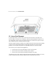
Hardware Installation 2 Hardware Installation An AP-7131 or AP-7131N access point installation includes mounting the access point, connecting the access point to the network, connecting antennae and applying power. Installation procedures vary for different environments. Both an AP-7131 and AP-7131N model access point have the following port designations: • • GE1/POE - LAN port GE2 - WAN Port 2.
4 AP-7131 Series Access Point: Installation Guide 2.3 Access Point Placement For optimal performance, install the access point away from transformers, heavy-duty motors, fluorescent lights, microwave ovens, refrigerators and other industrial equipment. Signal loss can occur when metal, concrete, walls or floors block transmission. Install the access point in an open area or add access points as needed to improve coverage. Antenna coverage is analogous to lighting.
Hardware Installation 2.3.1 Antenna Options Motorola supports two antenna suites for AP-7131 and AP-7131N models. One antenna suite supporting the 2.4 GHz band and another antenna suite supporting the 5 GHz band. Select an antenna model best suited to the intended operational environment of your access point. The AP-7131N model access point can be purchased in a three radio configuration.
6 AP-7131 Series Access Point: Installation Guide The 2.4 GHz antenna suite includes the following models: Part Number Antenna Type Approximate Gain (dBi) ML-2499-11PNA2-01R Wide Angle Directional 8.5 ML-2499-HPA3-01R Omni-Directional Antenna 3.3 ML-2499-BYGA2-01R Yagi Antenna 13.9 ML-2452-APA2-01 Dual-Band 3/4 ML-2452-PTA2M3X3-1 Facade with 6 Element Antenna Module 4.75/5.
Hardware Installation 2.3.2 Power Injector System The access point can receive power via an Ethernet cable connected to the GE1/POE (LAN) port. NOTE Single radio model access points always operate using a full power configuration. The power management configurations described in the table below only apply to dual radio models. For detailed information on the power management options available to the AP-7131, refer to the AP-7131 Series Product Reference Guide available at http://support.symbol.
8 AP-7131 Series Access Point: Installation Guide A separate Power Injector is required for each access point comprising the network. The Power Injector can be installed free standing, on an even horizontal surface or wall mounted using the power injector’s wall mounting key holes. The following guidelines should be adhered to before cabling the Power Injector to an Ethernet source and an access point: • • • ! Do not block or cover airflow to the Power Injector.
Hardware Installation 1. Connect the Power Injector to an AC outlet (110VAC to 220VAC). 2. Connect an RJ-45 Ethernet cable between the network data supply (host) and the Power Injector Data In connector. 3. Connect an RJ-45 Ethernet cable between the Power Injector Data & Power Out connector and the access point’s GE1/POE port. NOTE Cabling a Power Injector to the WAN port (GE2 port) renders the AP non-operational.
10 AP-7131 Series Access Point: Installation Guide
Hardware Installation To mount the access point on a wall using the provided template: 1. Xerox copy the template (on the previous page) to a blank piece of paper. Do not reduce or enlarge the scale of the template. ! CAUTION If printing the mounting template (on the previous page) from an electronic PDF, dimensionally confirm the template by measuring each value for accuracy. 2. Tape the template to the wall mounting surface.
12 AP-7131 Series Access Point: Installation Guide 11. Cable the access point using either the Power Injector solution or an approved line cord and power supply. For Motorola Power Injector installations: a. Connect a RJ-45 CAT5e (or CAT6) Ethernet cable between the network data supply (host) and the Power Injector Data In connector. b. Connect a RJ-45 CAT5e (or CAT6) Ethernet cable between the Power Injector Data & Power Out connector and the access point GE1/POE port. c.
Hardware Installation 2.4.2 Suspended Ceiling T-Bar Installations A suspended ceiling mount requires holding the access point up against the T-bar of a suspended ceiling grid and twisting the access point chassis onto the T-bar. The mounting tools (customer provided) and hardware required to install the access point on a ceiling T-bar consists of: • • Safety wire (recommended and customer supplied) Security cable (optional and customer supplied) To install the access point on a ceiling T-bar: 1.
14 AP-7131 Series Access Point: Installation Guide a. Connect a RJ-45 Ethernet cable between the network data supply (host) and the access point’s GE1/POE or GE2 port. b. Verify the power adapter is correctly rated according the country of operation. c. Connect the power supply line cord to the power adapter. d. Attach the power adapter cable into the power connector on the access point. e. Attach the power supply line cord to a power supply.
Hardware Installation 10. Rotate the access point chassis 45 degrees counter-clockwise. The clips click as they fasten to the T-bar. 11. The access point is ready to configure. For information on basic access point device configuration, see “Configuring “Basic” Device Settings” on page 26. NOTE 2.4.3 If the access point is utilizing remote management antennas, a wire cover can be used to provide a clean finished look to the installation. Contact Motorola for more information.
16 AP-7131 Series Access Point: Installation Guide NOTE Both the AP-7131 and AP-7131N are Plenum rated to UL2043 and NEC1999 to support above the ceiling installations. To ensure UL compliance and proper access point operation within the Air Handling Plenum, the access point must be installed with the bottom surface of the unit in contact with the un-finished surface of the ceiling tile. This will facilitate the positioning of the light pipe (described in the following pages) through the ceiling tile.
Hardware Installation 5. Create a light pipe path hole in the target position on the ceiling tile. 6. Use a drill to make a hole in the tile the approximate size of the access point LED light pipe. ! CAUTION Motorola recommends care be taken not to damage the finished surface of the ceiling tile when creating the light pipe hole and installing the light pipe. 7. Remove the light pipe’s rubber stopper (from the access point) before installing the light pipe. 8.
18 AP-7131 Series Access Point: Installation Guide 13. Align the ceiling tile into its former ceiling space. 14. Cable the access point using either the Power Injector solution or an approved line cord and power supply. For Motorola Power Injector installations: a. Connect a RJ-45 CAT5e (or CAT6) Ethernet cable between the network data supply (host) and the Power Injector Data In connector. b.
Hardware Installation 2.5 LED Indicators Both AP-7131 and AP-7131N model access points have six LEDs on the top of the access point housing, and one optional LED light pipe at the bottom of the unit. However, an AP-7131 model access point does not use LED 6, as no third radio is available. Five LEDs illuminate (on top of the housing) for dual radios models and four illuminate for single radio models. The access point utilizes two (different colored) lights below each LED.
20 AP-7131 Series Access Point: Installation Guide 2.5.1 Three Radio AP-7131N LEDs A three radio model AP-7131N has the following unique LED behavior: LED 1 LED 2 (LAN) LED 3 (WAN) Blinking Red indicates booting. Solid Red defines the diagnostic mode. White defines normal operation. Green defines normal GE1 operation. Green defines normal GE2 operation. LED 4 - 5 GHz LED 5 - 2.4 GHz Blinking Blinking Emerald Amber indicates indicates 802.11bg 802.11a activity. activity.
Hardware Installation 2.5.2 Dual Radio (2.4/5 Ghz) LEDs A dual radio (2.4/5 Ghz) model access point has the following unique LED behavior: LED 1 LED 2 (LAN) LED 3 (WAN) Blinking Red indicates booting. Solid Red defines the diagnostic mode. White defines normal operation. Green defines normal GE1 operation. Green defines normal GE2 operation. LED 4 - 5 GHz LED 5 - 2.4 GHz Blinking Blinking Emerald Amber indicates indicates 802.11bg 802.11a activity. activity.
22 AP-7131 Series Access Point: Installation Guide 2.5.3 Single Radio 2.4 Ghz LEDs A single 2.4 Ghz radio model has the following unique LED behavior: LED 1 LED 2 (LAN) LED 3 (WAN) LED 4 - 5 GHz LED 5 - 2.4 GHz LED 6 Blinking Red indicates booting. Solid Red defines the diagnostic mode. White defines normal operation. Green defines normal GE1 operation. Green defines normal GE2 operation. Off Blinking Emerald indicates 802.11bg activity. A 5 second Emerald and Yellow blink rate defines 802.
Hardware Installation 2.5.4 Single Radio 5 Ghz AP-7131 LEDs A single 5 Ghz radio model has the following unique LED behavior: LED 1 LED 2 LED 3 LED 4 - 5 GHz LED 5 - 2.4 GHz LED 6 Blinking Red indicates booting. Solid Red defines the diagnostic mode. White defines normal operation. Green defines normal GE1 operation. Green defines normal GE2 operation. Blinking Amber indicates 802.11a activity. A 5 second Amber and Yellow blink rate defines 802.11an activity.
24 AP-7131 Series Access Point: Installation Guide 2.5.5 Rear AP-7131 LED The LED on the rear (bottom) of the access point is optionally viewed using a single (customer installed) extended light pipe, adjusted as required to suit above the ceiling installations. The LED light pipe has the following color display and functionality LED 7 Blinking Red (160 msec) indicates a failure condition. Solid Red defines the diagnostic mode. White defines normal operation.
Basic Configuration The login screen displays. 2. Log in using admin as the default User ID and motorola as the default password. If the default login is successful, the Change Admin Password window displays. 3. Change the password. Enter the current password and a new admin password in fields provided, and click Apply.
26 AP-7131 Series Access Point: Installation Guide access point could be operating illegally unless set to operate in the correct country. Proceed to “Configuring “Basic” Device Settings” on page 26 to validate the country setting. NOTE Though the access point can have its basic settings defined using a number of different screens, Motorola recommends using the AP-7131 Quick Setup screen to define a minimum required configuration from one location. 3.
Basic Configuration 1. Select System Configuration -> Quick Setup from the menu tree, if the Quick Setup screen is not already displayed. 2. Select the System Configuration tab to define the access point’s system, WIPS server and radio configuration. NOTE Beginning with the 4.0 release of the access point firmware, WIPS functionality is no longer configured within a designated WIPS screen. The WIPS Server designation and radio configuration is now defined as part of the access point’s quick setup.
28 AP-7131 Series Access Point: Installation Guide b. Select the Country for the AP-7131’s country of operation. The access point prompts for the correct country code on the first login. A warning message also displays stating an incorrect country setting may result in illegal radio operation. Selecting the correct country is central to legally operating the access point.
Basic Configuration Radio Button Single Radio SKU Dual Radio SKU Three Radio SKU 2.4 GHz WLAN, 5.0 GHz WLAN & Sensor Not Available Not Available Radio 1 WLAN, Radio 2 WLAN, Radio 3 WIPS 2.4 GHz WLAN, & Sensor Not Available Radio1 WLAN, Radio 2 WIPS Radio 1 WLAN, Radio 2 WIPS, Radio 3 WIPS 5.0 GHz WLAN & Sensor Not Available Radio 1 WIPS, Radio 2 WLAN Radio 1 WIPS, Radio 2 WLAN, Radio 3 WIPS 2.4 GHz WLAN & 5.
30 AP-7131 Series Access Point: Installation Guide 5. Select the Quick Setup screen’s Network Configuration tab to define a minimum set of WAN or LAN configuration values. The WAN tab displays by default. a. Select the Enable WAN Interface checkbox to enable a connection between the access point and a larger network or outside world through the WAN port. Disable this option to effectively isolate the access point’s WAN connection. No connections to a larger network or the Internet will be possible.
Basic Configuration c. Specify an IP address for the access point’s WAN connection. An IP address uses a series of four numbers expressed in dot notation, for example, 190.188.12.1. d. Specify a Subnet Mask for the access point’s WAN connection. This number is available from the ISP for a DSL or cable-modem connection, or from an administrator if the access point connects to a larger network. A subnet mask uses a series of four numbers expressed in dot notation. For example, 255.255.255.
32 AP-7131 Series Access Point: Installation Guide to use the access point as a DHCP server over the LAN connection. Select the Bootp client option to enable a diskless system to discover its own IP address. NOTE Motorola recommends that the WAN and LAN ports should not be configured as DHCP clients at the same time. c. Enter the network-assigned IP Address of the access point. DNS names are not supported as a valid IP address for the access point. The user is required to enter a numerical IP address. d.
Basic Configuration a. Enter the Extended Services Set Identification (ESSID) and name associated with the WLAN. b. Use the Available On checkboxes to define whether the target WLAN is operating over the 802.11a/n or 802.11b/g/n radio. Ensure the radio selected has been enabled (see step 8). 8. Once the WLAN’s radio designations have been made, the radio must be configured in respect to intended 2.4 or 5 GHz radio traffic and the antennas used.
34 AP-7131 Series Access Point: Installation Guide 3.2.1 Configuring Basic Security For testing basic connectivity, there is no reason to configure a server supported authentication scheme. WEP 128 is described in this guide as a basic security scheme sufficient to protect the access point’s initial transmissions. For details on configuring more sophisticated authentication and encryption options available to the access point, refer to the AP-7131 Series Product Reference Guide.
Basic Configuration 3. Select the WEP 128 (104 bit key) checkbox.The WEP 128 Setting field displays within the New Security Policy screen. 4. Configure the WEP 128 Setting field as required to define the Pass Key used to generate the WEP keys. Pass Key Specify a 4 to 32 character pass key and click the Generate button. The access point, other proprietary routers and Motorola MUs use the same algorithm to convert an ASCII string to the same hexadecimal number.
36 AP-7131 Series Access Point: Installation Guide At this point, you can either restrict specific MU access to the access point (using the ACL) or test the access point for MU interoperability. 3.2.2 Excluding MUs from Association Optionally, use the access point Access Control List ACL to specify which MUs can or cannot gain access to an access point managed WLAN. By default, all mobile units can gain access.
Basic Configuration Refer to the Number of Responses value to assess the number of responses from the target MU versus the number of pings transmitted by the access point. Use the ratio of packets sent versus packets received to assess the link quality between MU and the access point. Click the Ok button to exit the Echo Test screen and return to the MU Stats Summary screen.
38 AP-7131 Series Access Point: Installation Guide 4 Specifications 4.1 AP-7131 Physical Characteristics An AP-7131 model access point has the following physical characteristics: Dimensions 5.50 in. Depth x 7.88 in. Width x 1.10 in. Height 14 cm Depth x 20.32 cm Width x 2.79 cm Height Housing Metal, plenum-rated housing (UL2043) Weight 2.
Specifications 4.3 Electrical Characteristics The AP-7131 and AP-7131N model access points have the following electrical characteristics: Operating Voltage 48VDC (compatible with POE .3af/.3at Draft) Operating Current Not to exceed 750mA @ 48VDC Power 48VDC, 0.75A 4.
40 AP-7131 Series Access Point: Installation Guide 4.5 AP-7131N Radio Characteristics An AP-7131N has the following radio characteristics: Operating Channels All channels from 4920 MHz to 5825 MHz except channel 52 -64 Channels 1-13 (EU), Channels 1-11 (US/Canada) Channel 14 (2484 MHz) Japan only Actual operating frequencies depend on regulatory Data Rates Supported 802.11g: 1,2,5.5,11,6,9,12,18,24,36,48, and 54Mbps 802.11a: 6,9,12,18,24,36,48, and 54Mbps 802.
Regulatory Compliance 5 Regulatory Compliance These devices (AP-7131 and AP-7131N) are approved under the Symbol Technologies brand; Symbol Technologies, Inc., is the Enterprise Mobility business of Motorola, Inc (“Motorola”). All Motorola devices are designed to be compliant with rules and regulations in locations they are sold and will be labeled as required. Any changes or modifications to Motorola equipment, not expressly approved by Motorola, could void the user's authority to operate the equipment.
42 AP-7131 Series Access Point: Installation Guide Safety in Hospitals Wireless devices transmit radio frequency energy and may affect medical electrical equipment. When installed adjacent to other equipment, it is advised to verify that the adjacent equipment is not adversely affected. RF Exposure Guidelines Safety Information The device complies with Internationally recognized standards covering human exposure to electromagnetic fields from radio devices.
Regulatory Compliance Radio Frequency Interference Requirements—FCC This equipment has been tested and found to comply with the limits for a Class B digital device, pursuant to Part 15 of the FCC rules. These limits are designed to provide reasonable protection against harmful interference in a residential installation.
44 AP-7131 Series Access Point: Installation Guide CE Marking and European Economic Area (EEA) The use of 2.4GHz RLAN’s, for use through the EEA, have the following restrictions: • • • Maximum radiated transmit power of 100 mW EIRP in the frequency range 2.400 -2.4835 GHz. France outside usage, the equipment is restricted to 2.400-2.45 GHz frequency range. Italy requires a user license for outside usage.
Regulatory Compliance Declarações Regulamentares para AP7131N - Brasil Nota: A marca de certificação se aplica ao Transceptor, modelo AP-7131N. Este equipamento opera em caráter secundário, isto é, não tem direito a proteção contra interferência prejudicial, mesmo de estações do mesmo tipo, e não pode causar interferência a sistemas operando em caráter primário. Para maiores informações sobre ANATEL consulte o site: www.anatel.gov.
46 AP-7131 Series Access Point: Installation Guide Wireless device operate in the frequency band of 5.25-5.35 GHz, limited for Indoor use only. 在 5.25-5.35 秭赫頻帶內操作之無線資訊傳輸設備,限於室內使用 Korea For a radio equipment using 2400~2483.5MHz or 5725~5825MHz, the following two expression should be displayed; 1. This radio equipment can be interfered during operation. 당해 무선설비는 운용 중 전파혼신 가능성이 있음 2. This radio equipment cannot provide a service relevant to the human life safety.
Waste Electrical and Electronic Equipment (WEEE) 6 Waste Electrical and Electronic Equipment (WEEE) English: For EU Customers: All products at the end of their life must be returned to Symbol for recycling. For information on how to return product, please go to: http://www.symbol.com/environmental_compliance. Dansk: Til kunder i EU: Alle produkter skal returneres til Symbol til recirkulering, når de er udtjent. Læs oplysningerne om returnering af produkter på: http://www.symbol.
48 AP-7131 Series Access Point: Installation Guide Nederlands: Voor klanten in de EU: alle producten dienen aan het einde van hun levensduur naar Symbol te worden teruggezonden voor recycling. Raadpleeg http://www.symbol.com/ environmental_compliance voor meer informatie over het terugzenden van producten. Português: Para clientes da UE: todos os produtos no fim de vida devem ser devolvidos à Symbol para reciclagem. Para obter informações sobre como devolver o produto, visite: http:/ /www.symbol.
Motorola’s Enterprise Mobility Support Center 7 Motorola’s Enterprise Mobility Support Center If you have a problem with your equipment, contact Enterprise Mobility support for your region. Contact information is available at: http://support.symbol.com/support/.
50 AP-7131 Series Access Point: Installation Guide 8 AP-7131 Series ROHS Compliance 有毒有害物质或元素 部件名称 (Parts) 铅 (Pb) 汞 (Hg) 镉 (Cd) 六价铬 (Cr6+) 多溴联苯 (PBB) 多溴二苯醚 (PBDE) 金属部件 (Metal Parts) X O O O O O 电路模块 (Circuit Modules) X O O O O O 电缆及电缆组件 (Cables and Cable Assemblies) X O O O O O 塑料和聚合物部件 (Plastic and Polymeric Parts) O O O O O O 光学和光学组件 (Optics and Optical Components) O O O O O O 电池 (Batteries) O O O O O O O:表示该有毒有害物质在该部件所有均质材料中的含量均在 SJ/T11363-2006 标准规定的限量要求
MOTOROLA INC 1303 E. ALGONQUIN ROAD SCHAUMBURG, IL 60196 http://www.motorola.