O5 Control Head User's Guide
This declaration is applicable to your radio only if your radio is labeled with the FCC logo shown below. DECLARATION OF CONFORMITY Per FCC CFR 47 Part 2 Section 2.1077(a) Responsible Party Name: Motorola, Inc. Address: 8000 West Sunrise Boulevard Plantation, FL 33322 USA Phone Number: 1-888-567-7347 Hereby declares that the product: Model Name: XTL 5000 conforms to the following regulations: FCC Part 15, subpart B, section 15.107(a), 15.107(d) and section 15.
Product Safety and RF Exposure Compliance ! Caution Before using this product, read the operating instructions for safe usage contained in the Product Safety and RF Exposure booklet enclosed with your radio. ATTENTION! This radio is restricted to occupational use only to satisfy FCC RF energy exposure requirements.
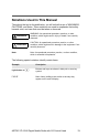
Notations Used in This Manual Throughout the text in this publication, you will notice the use of WARNINGS, CAUTIONS, and Notes. These notations are used to emphasize that safety hazards exist, and care that must be taken or observed. ! WARNING WARNING: An operational procedure, practice, or other condition, which might result in injury or death if not carefully observed.
Notes v
Contents O5 Control Head Foldout Page . . . . . . . . . . . . . . . . . . i Declaration of Conformity .................................................................. ii Computer Software Copyrights .........................................................iii Documentation Copyrights ................................................................iii Disclaimer .........................................................................................iii Notations Used in This Manual .......................
Initiating an Emergency Alarm ..................................................20 Initiating an Emergency Call .....................................................20 Initiating an Emergency Call and Alarm ....................................21 Initiating a Silent Emergency Alarm ..........................................22 Special Considerations for Emergencies ..................................22 Scan Operation ................................................................................
Selecting a Conventional Talkgroup ......................................... 51 Conventional Talkaround ................................................................ 52 Talk Direct (Mobile-To-Mobile) ................................................. 52 Selective Calls (Digital Modes Only) ............................................... 52 Answering a Selective Call ....................................................... 53 Initiating a Selective Call ......................................................
Troubleshooting . . . . . . . . . . . . . . . . . . . . . . . . . . . . . 79 Accessories. . . . . . . . . . . . . . . . . . . . . . . . . . . . . . . . . 81 Antennas .........................................................................................81 Bull Horns for Siren and Public Address .........................................83 Cables .............................................................................................83 Microphones .......................................................
Introduction Using Your Radio: The Basics This chapter gives you the basic knowledge you need in order to use your radio.
Introduction Getting Started The ASTRO® XTL™ 5000 Digital Mobile Radio is among the most sophisticated two-way radios available. It can operate in the following frequency ranges: VHF UHF 700/800 MHz 136-174 MHz 380-470 MHz 762-776 MHz 450-520 MHz 794-806 MHz 806-825 MHz 851-870 MHz These channels provide maximum communications capability under varying operating conditions.
Introduction Note: In this manual— Analog mode refers to a mode that uses traditional, non-ASTROdigital signaling. ASTRO mode refers to a mode that uses ASTRO digital signaling. Your ASTRO XTL 5000 Digital Mobile Radio utilizes Motorola’s revolutionary FLASHport™ technology. This allows your radio’s capabilities to be flexible, because FLASHport makes it possible to add software that drives these capabilities both at the time of purchase and later on.
Introduction Identifying Your Radio The ASTRO XTL 5000 Digital Mobile Radio has two major components: the radio unit installed in your vehicle and the control head that is used to activate various radio features. Keep the foldout page opened for reference as you read this manual. Your radio has the following control head: O5 Control Head The O5 has the rotary Mode and Volume knobs, 5 programmable menu buttons, a menu navigation button, and a 3-line, 14-character, fully bitmapped display (page i).
Introduction Turning On the Radio Do the following: • Turn the radio on with a short press of the power button in the lower left corner of the control unit. After a short time, the red, green and yellow LED’s light up, indicating that the radio is powering up. The display then shows XTL 5000. When the radio is fully powered on, the Zone and Channel text and menu items is displayed. The backlight will turn on to the last selected color and dim level.
Introduction Setting the Volume Rotate the Volume knob clockwise to increase the volume and counterclockwise to decrease the volume. Adjusting the Display Brightness Press the dimmer button (DIM) to change the display brightness to one of four levels: • Off to high • High to medium • Medium to low • Low to off In Off, both the display and backlight are off (used for surveillance operations).
Introduction Trunked Modes or Conventional Channels Depending on how your radio is programmed, you can select conventional channels or trunked talkgroup. Conventional channels consist of a transmit and receive frequency pair, an associated squelch code pair, and a time-out timer value. See “Conventional Radio Features” on page 47. Trunked modes consist of the system/announcement group/talkgroup combination and a time-out timer value. See “Trunking Operation” on page 61.
Introduction Display Status The control head display indicates your selected mode, or the currently active receive mode when scan is on. Feature Control You can turn the various radio features on or off, change modes, and adjust the volume. To exit a feature, such as phone, press the HOME button. Alert Tones Tone Type Name Two highpitched tones Private Conversation™ Indicate that a private call has been received.
Introduction Tone Type Name Description A series of two short, high-pitched tones Automatic Call Back Indicate that a channel is now available for your previously requested transmission. A series of two short, high-pitched tones (same as automatic call back) Talk Permit (optional) Indicate, when you press the microphone PTT button, that the system is accepting your transmission.
Introduction Tone Type Name Description Single, short, high-pitched tone Valid Key Indicates that you pressed a valid key, or you entered a feature configuration state, or you are receiving or transmitting in the clear mode on secure models (with TX Clear Alert Tones enabled). Single, lowpitched tone Invalid Key Indicates that you tried to make an invalid key press, or that an emergency alarm, reprogram request, or status/ message was not acknowledged.
Basic Operating Procedures Basic Functions This chapter shows you how to access the radio’s basic functions and includes the following topics: • Selecting the Zone or Mode (page 12) • Selecting the Home Mode (page 14) • Transmitting (Conventional Modes Only) (page 15) • Transmitting (Trunked Modes Only) (page 15) • Selecting the Transmit Level (page 16) • Monitoring Conventional Mode Activity (page 16) • Adjusting the Squelch Level (page 17) ASTRO XTL 5000 Digital Mobile Radio with O5 Control
Basic Operating Procedures Selecting the Zone or Mode A zone is a grouping of modes. A mode is a group of characteristics such as transmit/receive frequencies, Private-Line™ codes, radio parameters, and an alphanumeric name. Selecting or Changing the Zone 1 Press the 2 Press the button to scroll to the ZONE softkey. button below ZONE. The display shows the current zone and mode. 3 Press the 4 Press the or until the desired zone is displayed.
Basic Operating Procedures Selecting or Changing a Mode in the Current Zone To access a mode in the current zone, do the following: • Rotate the Mode knob until the display shows the desired mode name. OR 1 Press and hold 2 Press the to scroll to the CHAN softkey. below CHAN. The display shows the current zone and mode. 3 Rotate the Mode Knob until the desired channel in the current zone is displayed. 4 Press the or PTT button to save the displayed channel as the new home (default) channel.
Basic Operating Procedures Selecting the Home Mode This feature must first be enabled by a qualified radio technician. Press the HOME button to select the home mode contained within the home zone, from any other zone and mode in the radio.
Basic Operating Procedures Transmitting (Conventional Modes Only) 1 Lift the microphone off-hook, and listen for activity on that mode. 2 If you hear no activity, press and hold the microphone PTT button. Transmitting (Trunked Modes Only) 1 Lift the microphone off-hook, and press the microphone PTT button. 2 Do one of the following: • If you hear three quick tones, or if you hear no tone and the red XMIT (transmit) indicator lights steadily, then proceed with your message.
Basic Operating Procedures Selecting the Transmit Power Level The PWR softkey lets you select (toggle) the transmit power level. Press the PWR softkey. The display momentarily shows POWER LOW or POWER HIGH to indicate the transmit power level selected. Monitoring Conventional Mode Activity This feature allows you to monitor channel traffic on conventional channels by defeating the coded squelch. This feature must first be enabled by a qualified radio technician or system administrator.
Basic Operating Procedures Adjusting the Squelch Level Your radio’s ability to transmit or receive signals varies as you move away from or close to your base station. You can adjust your radio’s squelch to improve its ability to receive transmissions. Do the following: 1 Press the • or button to scroll to the MON softkey. Press and hold the button below MON. The display shows SQUELCH XX, where XX is a squelch level setting of 0 to 15. 2 Press to return to the selected channel.
General Radio Features Often-Used Features This chapter shows you how to access the most frequently used features.
General Radio Features Emergency Call and Alarm The emergency call and alarm features allow you to have priority channel access and/or send an emergency data transmission to the dispatcher in an emergency situation. The desired type of emergency feature—alarm, call, call and alarm, or silent alarm—can be preprogrammed by a qualified radio technician. The radio must be turned on to activate any emergency feature.
General Radio Features Initiating an Emergency Alarm The emergency alarm feature sends a data transmission to alert the dispatcher of your emergency condition and identify your unit ID. Press the emergency button. A tone sounds and the display alternates EMERGENCY with the current zone/channel. For trunking modes, a high-pitched tone indicates that the alarm has been received by the trunked system’s central controller. A dispatcher acknowledgment ACK RECEIVED display follows.
General Radio Features Initiating an Emergency Call and Alarm If the radio has both emergency call and alarm features, it automatically proceeds to the call mode after the alarm is acknowledged. 1 Press the emergency button to activate the emergency call/ alarm feature. The display begins alternating EMERGENCY with the current zone/channel. For trunking modes, a high-pitched tone sounds, indicating that the alarm has been received by the trunked system’s central controller.
General Radio Features Initiating a Silent Emergency Alarm 1 Press the emergency button to activate the silent alarm feature. During a silent emergency alarm, there are no display changes, and the receiver audio mutes so that no indication is given that an emergency alarm has been sent. 2 To exit the silent alarm mode, press and hold the emergency button until a tone sounds.
General Radio Features Scan Operation The scan feature allows you to monitor activity on different conventional or trunked modes by scanning a scan list of modes. The modes to be scanned in a scan list are programmed by a qualified radio technician. You can select the modes to be scanned in a scan list if operator-selectable scan is enabled.
General Radio Features Turning On Scan Do the following: 1 Press the 2 Press the button to scroll to the SCAN softkey. button below SCAN. The Scan indicator lights and a list of modes is scanned for activity. The text display area will indicate SCAN ON if scan is currently enabled or SCAN OFF if scan is just been turned off. When a scanned mode becomes active, the display changes to show the active mode name, the appropriate priority indicator lights, and the radio unmutes.
General Radio Features Turning Scan On While Disregarding the Squelch Code (Conventional Modes Only) Do the following: 1 Press the button to scroll to the MON softkey. 2 Press the 3 The brief MONITOR ON display indicates that the radio is disregarding the squelch code. button below MON. Note: While scanning for activity, you can still receive fleetwide, system-wide, dynamic regrouping, incoming telephone interconnect and Private Conversation/Call Alert calls.
General Radio Features Viewing a Scan List 1 Press and hold the SCAN softkey until the Scan indicator blinks and a beep is heard. The radio suspends scanning while a scan list is being reviewed. 2 Press the button to scroll to the VIEW softkey. 3 Press the 4 Press the 5 Press the button below SCAN. The radio suspends scanning while a scan list is being reviewed. 6 Press the scan list.
General Radio Features Transmitting While Scan Is On Radio Programmed for Talkback Scan Press the microphone PTT button to transmit on the mode indicated by the display. The radio does not begin scanning again for a predetermined hang time (programmable by a qualified radio technician) after you release the PTT button, allowing the other party to respond.
General Radio Features Temporarily Deleting a Nuisance Mode with Scan On To temporarily delete a mode that you do not wish to hear (nuisance mode), press the NUIS softkey by searching for it with the help of or . You can delete undesired modes. Note: Priority modes, the selected mode, and the designated transmit mode cannot be deleted. Restoring a Nuisance Mode To restore the original scan list, do one of the following: • Turn scan off, then on. • Change modes.
General Radio Features Changing Mode Priorities While Scan Is On When active, this dynamic priority feature allows you to change the priority of a non-priority mode in the scan list to priority 2. 1 Press DYNP softkey to change the priority of a nonpriority channel in the scan list to priority 2. 2 Press the HOME button momentarily to exit the scan list and resume scanning. Note: You cannot alter the status of the priority 1 member.
General Radio Features Programming a Scan List To program a scan list, operator-selectable scan list members first must be enabled in the radio programming by a qualified radio technician. Adding a Channel to the Scan List 1 Press the button to scroll to the PROG softkey. 2 Press the 3 Press the 4 Press the button below SCAN. The scan indicator blinks and a good-key chirp is heard. 5 Press the scan list. button below PROG. button to scroll to the SCAN softkey.
General Radio Features Deleting a Channel from the Scan List Do the following: 1 Press the button to scroll to the PROG softkey. 2 Press the 3 Press the 4 Press button below SCAN. The scan indicator blinks and a good-key chirp is heard. 5 Press the or button or Mode knob to locate the channel to be deleted. button below PROG. button to scroll to the SCAN softkey. Press the SEL softkey momentarily to scroll through the available priority choices until the priority choice disappears.
General Radio Features Hang Up Box (HUB) To temporarily suspend Scan Mode operation, remove the microphone from the Hang Up Box (HUB). You are allowed to use the microphone while scan is suspended. Priority Member scanning is not suspended, however. This feature applies to all Scan Lists and Scan Types. Scan is resumed once the microphone is returned to the holding clip and the preprogrammed hang time has elapsed.
General Radio Features Permanent Horn and Lights 1 Press the H/L softkey momentarily. The last selected alarm(s) are enabled. The display briefly shows the enabled alarms, and then reverts back to the selected mode. 2 Press the H/L softkey a second time to turn off the alarm(s). Changing the Selected Alarms 1 Press and hold the H/L softkey until a tone sounds and the display indicates the currently selected alarm.
General Radio Features Receiving a Call While Alarms Are Turned On When a call is received, the vehicle’s horn sounds for four seconds, and/or the car lights turn on for 60 seconds. The time interval can be modified by a qualified radio technician. The display alternates between the type of call received (CALL, PAGE, or PHONE) and the selected mode name. Turning Off Non-Rearmable External Alarm 1 To turn off the external alarm(s), press the PTT button or any control-head button.
General Radio Features Time-Out Timer Your ASTRO XTL 5000 Digital Mobile Radio provides a time-out timer function that prevents locking up a repeater or channel by prolonged keying of the transmitter. You cannot transmit longer than the preset timer setting. If you attempt to do so, the radio automatically stops your transmission, and you hear a talk-prohibit tone. Note: You will hear a brief, low-pitched, warning tone four seconds before the transmission times out.
General Radio Features Telephone Interconnect List (Conventional and Trunking) With any of the control heads, you can initiate and receive telephone calls if the system is properly equipped. All calls between the mobile operator and the land line are private, regardless of who initiates the call. All control heads feature a phone list capability of up to 100 preprogrammed phone numbers. The radios can be programmed by a qualified radio technician so that a name can be assigned to each number in the list.
General Radio Features Initiating a Telephone Call from the List 1 Press the PHON softkey momentarily to select the phone function. A valid-key chirp is heard. The display shows the last number dialed or a blank scratchpad appearing as a series of dashes. 2 Press the or button to locate the number you want to call. The display first shows the name, and then the number. 3 Press the PTT button. The display shows the number that is automatically dialed.
General Radio Features Unlimited Telephone Interconnect Calling a Phone Number Not in the List 1 Press the or button to access the PHON feature. Press the softkey under the phone feature. 2 Enter the desired phone number from the optional keypad mic. The display updates as the numbers are entered. 3 Press Enter on the keypad mic to make the call 4 When your party answers, press the PTT button to talk, and release it to listen.
General Radio Features Storing a Number in the List 1 Press and hold the PHON softkey to select the phone programming function. 2 Use the navigation keys, to change. 3 Press the SEL softkey to edit the number in the display. 4 Enter the new phone number on the keypad. or to locate the number you want Note: To backspace, press the # button twice or the Mode down button once. Enter a pause by pressing the * button, then the # button. 5 Press the SEL softkey to store the new number.
General Radio Features Editing a Name in the List 1 Press and hold the PHON softkey to enter the phone ID list programming. The Phon indicator flashes and a high-pitched tone sounds. 2 Use the navigation keys, want to change. or to locate the list member you OR Use the numbered keys to go immediately to the location of a member in the list. For example, press 2 to go to the second member in the list; press 1 and 0 to go to the tenth member in the list, and so on.
General Radio Features • To delete characters, press the Mode down to move backwards over existing characters. rocker switch When the last character on the display has been erased, rocker switch again to leave the press the Mode down name-edit mode, without making any changes, and begin the procedure again at step 2. 4 To save the changes, press and hold the SEL softkey. Note: Press the SEL softkey momentarily to confirm changes to a number in the list.
General Radio Features Table 1: Entering Characters Using the Keypad Number of times the key is pressed 42 Key 1 2 3 4 5 6 7 0 0 1 1 2 A B C 2 a b c 3 D E F 3 d e f 4 G H I 4 g h i 5 J K L 5 j k l 6 M N O 6 m n o 7 P Q R S 7 p q 8 T U V 8 t u v 9 W X Y Z 9 w x * * / + - # # 8 9 r s y z
General Radio Features Call Alert Page (Conventional and Trunking— Digital Modes Only) The Call Alert feature allows a radio to selectively alert another radio, and to determine whether or not that radio received the alert. A Call Alert page can be initiated after an unsuccessful Private Conversation call or as a separate feature. The O5 Controller Head is capable of responding to a Call Alert initiated by another radio. It features a unique list of up to 100 preprogrammed ID numbers.
General Radio Features Sending a Call Alert Page 1 Press the PAGE softkey. The Page indicator lights and a valid-key chirp sounds. The display shows the last transmitted/received unit ID number. 2 Select a radio in one of the following ways: • From the ID number list: – Do nothing if you want to call the unit ID currently displayed. OR – Use the prestored list by using the navigation keys to locate the name/ID you want to call.
General Radio Features 4 Choose one of the following: • When the called radio acknowledges the page, four additional tones sound and the display changes to ACK RCVD. The radio returns to normal operation. • If you are out of the range of the system, a low-pitched tone sounds. Try again by pressing the PTT button or or the SEL softkey, OR Press the HOME button or the PAGE softkey to return to normal operation.
General Radio Features Notes 46
Conventional Radio Features Features Used in Conventional Operation This chapter shows you how to access features available in conventional operation.
Conventional Radio Features Status Calls (Digital Modes Only) Radio status calls are used to inform the dispatcher of the present state of the mobile unit. For example, a status might be ENROUTE or AT SITE. Status names are field programmable. Each radio can have up to 8 separate statuses. Sending a Status Call 1 Press the STS softkey, and the display shows the lastacknowledged status name.
Conventional Radio Features • If there is no acknowledgment, do one of the following: Press the microphone PTT button to resend the status transmission. OR Press the HOME button to return to normal dispatch operation.
Conventional Radio Features Smart PTT Smart PTT is a per-mode feature that gives the system manager better control of radio operations. When smart PTT is enabled in your radio, you will not be able to transmit on an active mode. If you try to transmit (press the PTT button) on a busy or active smart PTT channel, a continuous tone sounds until you release the PTT button, and the transmission is inhibited. The yellow BUSY LED lights when the radio is receiving to indicate that the mode is busy.
Conventional Radio Features Selecting a Conventional Talkgroup The Talkgroup Select feature allows you to manually select any one of the available talkgroups. 1 Press the TGRP softkey. The display changes to show the last-selected talkgroup. 2 Rotate the Mode knob to choose a different talkgroup. 3 Press the SEL softkey to save the talkgroup. The radio returns to the home display. Note: To select the default talkgroup, press the SEL softkey while the radio displays PRESET.
Conventional Radio Features Conventional Talkaround Talk Direct (Mobile-To-Mobile) To talk directly to another unit without going through the conventional repeater system: 1 Press the DIR softkey momentarily. The Dir indicator lights, indicating that the radio is now transmitting directly to another unit. 2 To return to repeater operation, press the DIR softkey again. The Dir indicator goes out.
Conventional Radio Features Answering a Selective Call When a Selective Call is received, two high-pitched tones sound and the display alternates between CALL RECEIVED and the home display. 1 Press the CALL softkey within 20 seconds of receiving the call. (This time is programmable by a qualified radio technician.) The display shows the ID number of the calling unit. 2 To respond to the call, press the PTT button and talk.
Conventional Radio Features Initiating a Selective Call To initiate a Selective Call, select a unit to call, then place the call. 1 Press the CALL softkey. The Call indicator lights, and the display shows the last transmitted/received unit ID number. 2 Select a unit in one of the following ways: • From the ID number list: – Do nothing if you want to call the unit ID currently displayed. OR – Use the prestored list by using the navigation keys to locate the name/ID you want to call.
Conventional Radio Features 4 Choose one of the following conditions that applies to your current call: • If the receiving unit answers, identify yourself and begin your Selective Call. • If, after a programmable time period, you are not connected, the display shows NO ACKNOWLEDGE and a momentary, lowpitched tone sounds. Try again, or press the HOME button to return to normal operation. • If you are out of the system’s range, a low-pitched tone sounds.
Conventional Radio Features Viewing Your Unit ID Number 1 Press the CALL softkey momentarily to select the Selective Call feature. The Call indicator lights. 2 Do one of the following: • Use the left navigation key to locate the MY ID display. The display will alternate between MY ID and your ID number. 3 56 To return to normal operation, press the HOME button. .
Conventional Radio Features Storing a Unit ID Number in the List The Selective and Call Alert page features share the same prestored list of units’ IDs. 1 Press and hold the CALL softkey to review the Call ID list. The Call indicator flashes and a high-pitched tone sounds. 2 Use the navigation keys to locate the list member you want to change. 3 Press the NAME softkey to store a name OR press the NUM softkey to store a number. 4 Use the keypad mic to update the entry.
Conventional Radio Features Editing a Name in the List The Selective Call and Call Alert page features share the same prestored list of unit IDs. 1 Press and hold the CALL or PAGE softkey to enter the Call ID list. The Call indicator flashes and a high-pitched tone sounds. 2 Use the navigation keys to locate the list member you want to change. OR Use the numbered keys to go immediately to the location of a member in the list.
Conventional Radio Features • To delete characters, press the down navigation key to move backwards over existing characters. When the last character on the display has been erased, press the down navigation key again to leave the nameedit mode, without making any changes, and begin the procedure again at step 2. 5 To save the changes, press and hold the SEL softkey. Note: Press the SEL softkey momentarily to confirm changes to a number in the list.
Conventional Radio Features Notes 60
Trunking Operation Features Used on Trunking Systems This chapter shows you how to access features available on trunking systems.
Trunking Operation Enhanced Private Conversation (Digital Modes Only) The enhanced Private Conversation feature not only allows you to carry on a conversation that is heard only by the two parties involved, but also enables you to determine whether the unit you are calling is in service. The O5 Control Head is capable of responding to a Private Conversation call initiated by another radio. It features a unique list of preprogrammed ID numbers.
Trunking Operation Initiating an Enhanced Private Conversation Call To initiate an Enhanced Private Conversation Call, select a unit to call, then place the call. 1 Press the CALL softkey. The Call indicator lights, and the display shows the last transmitted/received unit ID number. 2 Select a unit in one of the following ways: • From the ID number list: – Do nothing if you want to call the unit ID in the display.
Trunking Operation 4 Choose one of the following conditions that applies to your current call: • If the receiving unit answers, identify yourself and begin your Private Conversation. • If, after a programmable time period, you are not connected, the display shows NO ACKNOWLEDGE and a momentary, lowpitched tone sounds. Try again, or press the HOME button to return to normal operation. • If you are out of the system’s range, a low-pitched tone sounds.
Trunking Operation Failsoft If the trunked system’s central controller fails for any reason, the radio indicates failsoft. In this condition, the radio transmits and receives on a pre-determined frequency in a conventional mode. Failsoft ensures that you will have communications capability at all times. Radios can be programmed by the system administrator so units that normally communicate on the same trunked mode will be assigned to the same failsoft repeater frequency.
Trunking Operation Dynamic Regrouping (Digital Modes Only) The dynamic regrouping feature allows the dispatcher to temporarily reassign selected individuals, operating in separate trunked talkgroups, into a single group so that they can communicate. Receiving a Dynamic Regrouping ID Assignment When your unit receives a dynamic regrouping ID assignment, a unique chirp sounds to alert you that your unit has been dynamically regrouped. The display shows the new dynamic mode name assignment.
Trunking Operation Selecting Enable and Disable (Digital Modes Only) The dispatcher may classify regrouped units into one of two categories: select-enabled or select-disabled. Select-enabled Units are free to make mode changes to any of the available talkgroups, including the dynamic group. Select-disabled Units cannot change modes because the dispatcher has specifically chosen to force the unit to remain in the dynamic mode.
Trunking Operation SmartZone The SmartZone® feature extends communications beyond the reach of a single-trunked site (antenna location) when operating in a SmartZone system. SmartZone units provide expanded wide-area coverage. SmartZone automatically switches the radio to a different site when the current site signal becomes unacceptable. This usually happens when the vehicle in which the radio is located is driven out of the range of one site, and into the range of another.
Trunking Operation Locking onto a Site In areas that commonly have weak signals, use the SmartZone lock function to prevent the radio from automatically scanning for a new site. 1 Press the SITE softkey momentarily to display the current lock status. Either the display shows SITE LOCKED or SITE UNLOCKED. Press the HOME button or SITE softkey again to return to normal operation. 2 To change the locked or unlocked condition, press and hold the SITE softkey until a tone sounds and the display changes.
Trunking Operation Out-of-Range Indication The out-of-range display/audible indication feature can be enabled by a qualified radio technician. The display alternately shows OUT OF RANGE and the current selected mode, and a low-pitched tone sounds every six seconds: • When the radio is out of range of the system and can no longer lock onto the control channel OR • When the radio is in failsoft and cannot lock onto the failsoft channel.
Trunking Operation Trunked Announcement The announcement capability allows a user to make announcements to the entire user group, as well as monitor talkgroup calls and other announcements. Announcement calls are handled in two different ways, depending on the trunked central controller configuration. The two types are called ruthless and non-ruthless preemption. • Ruthless Preemption: When a ruthless preemption announcement call is initiated, the requesting radio begins transmitting immediately.
Trunking Operation Notes 72
Secure Operation Features Available on Secure XTL 5000 This chapter covers features available on XTL 5000 Digital Mobile Radios with secure encryption.
Secure Operation Receiving a Private Message 1 Select a mode by rotating the Mode knob. 2 Using the Volume Knob, adjust the volume to a comfortable listening level. In conventional modes and, if enabled, in trunking modes, the BUSY light blinks and the radio unmutes when the radio is receiving a private message. Note: The secure on/off state does not affect received messages. The radio automatically receives coded or clear messages.
Secure Operation System Considerations • Trunked Systems only: If you press the PTT button when no secure-voice channel is available, the display shows NO SECURE, and a continuous talk-prohibit tone sounds until you release the PTT button. • Analog trunking systems: You are not allowed to change from a secure transmission to a clear transmission during a secure trunked call.
Secure Operation Selecting an Encryption Key (Conventional Only) The Select Key feature allows you to manually select any one of the 16 encryption keys. If the current mode is programmed with key selection being strapped to force the current mode to use a predetermined key, the Select Key menu will not appear as a Secure menu item. 1 Press and hold down the SEC softkey until a tone sounds, which indicates entry into the Advanced Secure menu. 2 Use the navigation keys to locate the KEY SEL option.
Secure Operation 6 To abort this menu, press the HOME button or the PTT button. Pressing HOME exits the key-select menu without saving the selected key choice. Pressing the PTT button exits the menu without saving the selected key choice and allows the radio to transmit. When you abort the key-select menu, the radio uses the key that was selected prior to entry into the menu.
Secure Operation Selecting an Encryption Index (Conventional Only) The Select an Index feature allows you to select one or more groups of several encryption keys from among the available keys stored in the radio. For example, you could have a group of three keys structured to one index, and another group of three different keys structured to another index. By changing indices, you would automatically switch from one set of keys to the other.
Troubleshooting Troubleshooting The following are suggestions to assist you in troubleshooting possible operating problems. ! CAUTION The cables that connect to the rear of the radio could have live voltage on some of their pins. Do not remove or reconnect these cables. Only a qualified radio technician should perform this task. Service performed by unauthorized personnel may cause the radio to transmit an emergency alarm even if the unit is turned off.
Troubleshooting Notes 80
Accessories Motorola provides the following approved accessories to improve the productivity of your XTL 5000 mobile two-way radio. For a list of Motorola-approved antennas, batteries, and other accessories, visit the following web site: http://www.motorola.com/cgiss/index.shtml Antennas Part No. Description HAD4006_ VHF, 136–144 MHz, quarterwave whip, roof mount HAD4007_ VHF, 144–150.8 MHz, quarterwave, roof mount HAD4008_ VHF, 150.
Accessories 82 HAE4003_ UHF, 450–470 MHz, quarterwave whip HAE4004_ UHF, 470–512 MHz, quarterwave HAE4011_ UHF, 450–470 MHz, 3.5 db, roof mount HAE4012_ UHF, 470–495 MHz, 3.0 db, roof mount HAE4013_ UHF, 494–512 MHz, 3.0 db, roof mount HAE6010_ UHF, 380–433 MHz, 3.5 db gain HAE6011_ UHF, 380–433 MHz, 5.0 db gain HAE6012_ UHF, 380–433 MHz, quarterwave whip HAE6013_ UHF, 380–470 MHz, 2.
Accessories Bull Horns for Siren and Public Address Part No. Description TDN6251_ Round with chrome finish TDN6252_ Rectangular with chrome finish TDN6253_ Underhood with gray finish TDN6254_ Round with gray finish Cables Part No. Description HKN4191_ Power, high-power, dash-mount HKN4192_ Power, 20-ft., remote-mount HKN4356_ 17-ft. (W4/5/7/9) HKN6160_ Data, 6-ft., dash-mount (kit) HKN6161_ Data, 20-ft.
Accessories HKN6184A Cable, CH Programming (RS-USB) HKN6183A Cable, CH Programming (RS-232) HKN6184 Flash/Programming cable (USB) HKN6183 Flash/Programming cable (RS232) YLN1148_ Armored, for handset/hangup mic HMN4082A Armored, for handset/hangup mic Microphones Part No. Description HMN1079_ Motorcycle Palm D-Sub 9 connector HMN4081A Motorcycle Palm GCAI connector HMN4079_ Keypad Mic HMN6185A_ Standard palm Miscellaneous 84 Part No.
Accessories Remote Mounting Kits Part No. Description HLN6921A Remote-to-dash HLN6922A Dash-to-remote Speakers Part No. Description HSN4031_ 7.5 W external HSN4032_ 13 W external HSN4038_ 7.5 W remote weather-resistant HSN4039_ 13 W remote weather-resistant HSN6003_ Motorcycle, weather-resistant Trunnion Kits Part No. Description HLN6909_ Quick-release, high-power HLN6910_ Standard high-power HKN6186A Trunnion, CH Remote Mount HLN6861 HDWR Millenium St.
Appendix: Maritime Radio Use in the VHF Frequency Range Special Channel Assignments Emergency Channel If you are in imminent and grave danger at sea and require emergency assistance, use VHF Channel 16 to send a distress call to nearby vessels and the United States Coast Guard. Transmit the following information, in this order: 1 “MAYDAY, MAYDAY, MAYDAY.” 2 “THIS IS _____________________, CALL SIGN __________.
Appendix: Maritime Radio Use in the VHF Frequency Range Non-Commercial Call Channel For non-commercial transmissions, such as fishing reports, rendezvous arrangements, repair scheduling, or berthing information, use VHF Channel 9. Operating Frequency Requirements A radio designated for shipboard use must comply with Federal Communications Commission Rule Part 80 as follows: • on ships subject to Part II of Title III of the Communications Act, the radio must be capable of operating on the 156.
Appendix: Maritime Radio Use in the VHF Frequency Range Table A-1: VHF Marine Channel List (Continued) 88 Frequency (MHz) Channel Number Transmit Receive 8 156.400 – 9 156.450 156.450 10 156.500 156.500 11 156.550 156.550 12 156.600 156.600 13** 156.650 156.650 14 156.700 156.700 15** 156.750 156.750 16 156.800 156.800 17** 156.850 156.850 18 156.900 161.500 19 156.950 161.550 20 157.000 161.600 * 157.050 161.650 22 157.100 161.700 * 157.150 161.
Appendix: Maritime Radio Use in the VHF Frequency Range Table A-1: VHF Marine Channel List (Continued) Frequency (MHz) Channel Number Transmit Receive 67** 156.375 156.375 68 156.425 156.425 69 156.475 156.475 71 156.575 156.575 72 156.625 – 73 156.675 156.675 74 156.725 156.725 75 *** *** 76 *** *** 77** 156.875 – 78 156.925 161.525 79 156.975 161.575 80 157.025 161.625 * 157.075 161.675 * 157.125 161.725 * 157.175 161.775 84 157.225 161.825 85 157.
Glossary ACK Acknowledgment of communication. Channel A group of characteristics, such as transmit/ receive frequency pairs, radio parameters, and encryption encoding. Coded Squelch Tone Private-Line™ or Digital Private-Line. Used on conventional channels to make sure you hear only the communication meant for you. Control Channel In a trunking system, one of the channels that is used to provide a continuous, two-way/data communications path between the central controller and all radios on the system.
Glossary Hang Up Disconnect. Home Display The first display information after the radio completes its self test. LCD Liquid-Crystal Display. Mode A programmed combination of operating parameters; for example, a channel or talkgroup. Mode-Slaving Radio programmed to automatically give the proper operation for a given mode you have selected. Monitoring (Conventional Operation) Press a programmed monitor button to listen to another user active on the channel.
Glossary Squelch The muting of audio circuits when received signal levels fall below a pre-determined threshold. With carrier squelch, you hear all channel activity which exceeds the radio’s preset squelch level. Standby An operating condition whereby the radio’s speaker is muted but still continues to receive data. Talkgroup An organization (or group) of radio users who communicate with each other, using the same communication path.
Commercial Warranty and Service Limited Warranty MOTOROLA COMMUNICATION PRODUCTS I. WHAT THIS WARRANTY COVERS AND FOR HOW LONG: MOTOROLA INC.
Commercial Warranty and Service II. GENERAL PROVISIONS: This warranty sets forth the full extent of MOTOROLA'S responsibilities regarding the Product. Repair, replacement or refund of the purchase price, at MOTOROLA’s option, is the exclusive remedy. THIS WARRANTY IS GIVEN IN LIEU OF ALL OTHER EXPRESS WARRANTIES. IMPLIED WARRANTIES, INCLUDING WITHOUT LIMITATION, IMPLIED WARRANTIES OF MERCHANTABILITY AND FITNESS FOR A PARTICULAR PURPOSE, ARE LIMITED TO THE DURATION OF THIS LIMITED WARRANTY.
Commercial Warranty and Service V. WHAT THIS WARRANTY DOES NOT COVER: A) Defects or damage resulting from use of the Product in other than its normal and customary manner. B) Defects or damage from misuse, accident, water, or neglect. C) Defects or damage from improper testing, operation, maintenance, installation, alteration, modification, or adjustment. D) Breakage or damage to antennas unless caused directly by defects in material workmanship.
Commercial Warranty and Service J) Scratches or other cosmetic damage to Product surfaces that does not affect the operation of the Product. K) Normal and customary wear and tear. VI.
Commercial Warranty and Service Product. The foregoing states the entire liability of MOTOROLA with respect to infringement of patents by the Product or any parts thereof. Laws in the United States and other countries preserve for MOTOROLA certain exclusive rights for copyrighted MOTOROLA software such as the exclusive rights to reproduce in copies and distribute copies of such Motorola software.
Commercial Warranty and Service Notes 98
Index Symbols C 800 MHz frequencies ....................2 call answer phone ......................... 36 conventional talkgroup ............ 50 emergency .............................. 19 Enhanced Private Conversation .................. 54, 63 initiate emergency .......................... 20 Enhanced Private Conversation ................ 54, 63 from phone list ..................... 37 phone number not in list ......... 38 receiving when alarms turned on ..............................
Index D delete nuisance mode ........................28 scan list channel ......................31 digital trunking system considerations ..........................75 display, brightness adjustment ......6 dynamic regrouping receiving an ID assignment .....66 requesting ................................67 E edit name in list ...........................40 embedded signaling ......................2 emergencies, special considerations ..........................22 emergency call initiating ....................
Index edit name ................................40 phone, place call .....................37 scan .........................................23 store phone number ................39 telephone interconnect ............36 lock on a site, SmartZone ...........69 loss indication, secure operation .75 M mode analog .......................................3 ASTRO ......................................3 changing ..................................13 changing outside current zone 13 priorities, changing .............
Index autoscan ..................................23 indicator ...................................24 non-priority ...............................23 non-talkback ............................27 operation .................................23 operator-selectable ..................23 priority ......................................23 talkback ...................................27 transmit while on ......................27 turning on ................................24 scan list add a channel .......................
Index operation .................................61 status calls ..............................48 telephone interconnect list ......36 unlimited telephone interconnect ..........................38 turn on radio ......................................5, 6 scan .........................................24 U UHF frequencies ...........................2 units select-disabled ........................67 select-enabled .........................67 troubleshooting ........................
ASTRO® XTL™ 5000 Digital Mobile Radio with O5 Control Head O5 Quick Reference Card Product Safety and RF Exposure Compliance Before using this product, read the operating instructions for safe usage contained in the Product Safety and RF C a u t i o n Exposure booklet enclosed with your radio. ! ATTENTION! This radio is restricted to occupational use only to satisfy FCC RF energy exposure requirements.
Sending an Emergency Alarm or Call Press the emergency actuator (Emer button, footswitch, hidden pushbutton) to begin an emergency transmission. Alarm Type Indications/Actions Alarm and Call After ACK RECEIVED (see Non-Silent Alarm above) is displayed, the radio has priority voice-channel access. Press the PTT button and talk. For conventional modes, a silent or non-silent emergency alarm data transmission is sent.
Selecting Secure Mode Press and release the SEC softkey. The D indicator lights up. Selecting an Encryption Key 1 Press and hold the SEC softkey until a tone sounds. 2 Use the navigation keys to scroll to KEY SEL. 3 Press Sel to enter the Key Selection Menu. 4 Use the navigation keys to select desired key. 5 Press Sel to select key. 6 Press Home or the PTT button to quit. Selecting a Key Index 1 Press and hold the SEC softkey until a tone sounds.. 2 Use the navigation keys to scroll to INDX SEL.
ALERT TONES Type of Tone ALERT TONES (Continued) Explanation Type of Tone Name Explanation 1 Low-Pitched Tone Invalid Key Alert Name Feature button pressed is not valid in selected mode, or a Call Alert or emergency alarm was not acknowledged. 2 Short HighTones (after requesting a busy channel) upon pressing the PTT button) Automatic Call Back or Talk Permit Channel is available for previously requested transmission. System is accepting your transmission.
Motorola, Inc. 8000 West Sunrise Boulevard Ft. Lauderdale, FL 33322 MOTOROLA, the Stylized M Logo, and ASTRO are registered in the U.S. Patent and Trademark Office. All other product or service names are the property of their respective owners. © Motorola, Inc. 2005. All rights reserved. Printed in U.S.A.