
Service manual


68P81076C25-C July 1, 2002
Theory of Operation: Power Amplifiers 3-63
3.7.1.3 50-Watt Power Amplifiers
3.7.1.3.1 Transmitter
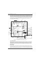
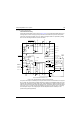
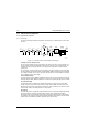
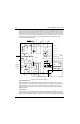
The 50-Watt ASTRO Spectra power amplifiers (PA's) are discussed in the following text. A block
diagram of the circuit is shown in Figure 3-22.
Figure 3-22. 50-Watt Power Amplifier Block Diagram
Transmit Low Level Amplifier (LLA)
NOTE: The minimum input drive level to the PA into J3850 is 10 mW. Refer to the synthesizer section
if input drive is less than 10 mW.
The LLA, the first stage of the of the PA, provides a gain that is a function of a control voltage. This
control voltage comes from the Regulator Power Control IC (RPCIC) on the command board. The
magnitude of the control voltage depends on PA output power, temperature, and final amplifier
current drain.
The LLA, Q3801, is unique in that its gain is controlled by varying the collector's current rather than
its voltage. Transistor Q3801 and associated circuitry (Q3806, Q3802, R3804, and R3818) are best
described as a voltage-controlled current source. This means that the collector current of Q3801 is
controlled by the magnitude of the control voltage. Proper operation of the LLA can be checked by
monitoring the voltage across the resistor R3804. The voltage should measure in the range of
0.1 V to 1.0 V, depending on the value of control voltage. A 0.1-V reading corresponds to a low
control voltage (1 to 5 V) and a 1.0-V reading corresponds to a high control voltage (up to control
voltage limit).
Predriver Stage
The second stage of the PA, Q3804, is the predriver. The purpose of this stage is to amplify the
output of the LLA to a level sufficient to drive the driver device, Q3850. Input power to this stage is
approximately 100 mW; output power from this stage is 1.0 Watt.
Driver Stage
The driver is a 1.2- to 15-Watt device. It is driven by the predriver device through a matching circuit
that consists of C3815, C3816, C3817, C3818, and L3811. A ferrite bead L3810, and a parallel
resistor, R3815, give the driver a zero-DC bias required for the driver's Class C operation, and
provides a low Q network to prevent unwanted oscillations. The network of L3851, L3854, C3858,
C3856, C3855, and R3850 provide A+ to the collector. L3851 and L3854 provide the DC path and
block RF from coming up the DC line. R3850 resistively loads down the collector at low frequencies,
preventing unwanted oscillations. C3856, C3855, C3858, and C3855 are bypass capacitors.
E3850
MALE SMB/
TAIKO DENKI
10 mW
Q3801
82D50
TX INJECTION
PREDRIVER
DRIVER
FINAL
AMPLIFIER
DIRECTIONAL
COUPLER
P.I.N. SWITCH
HARMONIC FILTER
ANTENNA
100 mW
1 W
12 W
65 W
CONTROL
VOLTS
K9.4
9.6V
Q3804
M9859
Q3850
25C28
Q3875
11L04
A+
A+
CURRENT
SENSE
TEMP
SENSE
DET
VOLTAGE
K9.4
55 W
E3852
RECEIVE
E3851
MINI UHF
CONTROLLED
TX BUFFER
MALE SMB/
TAIKO DENKI