
Service manual

68P81076C25-C July 1, 2002
Troubleshooting Procedures: ASTRO Spectra Procedures 4-7
4.1.4.1.2 Incorrect Values at U602 Pin 25 (MODULUS CONTROL)
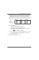
If the frequency is not 6.25 kHz (or 5.0 kHz for VHF), verify the proper VCO pin-shift logic. See VCO
block diagram (Figure 4-1) for pin-shift logic. Also, check the VCO feedback for approximately -10 to
5 dBm at proper VCO frequency. Use the following table:
If the VCO is running at approximately the correct level and frequency, proceed to “Incorrect Values
at U602, pin 27.”
4.1.4.1.3 Incorrect Voltage at Positive Steering Line
Verify that the VCO is running; check VCO feedback for -10 to 0 dBm. Verify that the feedback buffer
(if used) is working check U601-1.
4.1.4.1.4 Incorrect Values at U602, pin 27
Check prescaler (U601) operation; U601-40 should be:
EQUATION: F = F
vco
/(P or P+1)
4.1.4.2 Review of Synthesizer Fundamentals
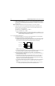
1. The synthesizer is a phase-locked loop system with a sample-and-hold phase detector.
2. In a locked system, the prescaler, in conjunction with the counters in the synthesizer chip,
counts the VCO frequency down to the reference frequency. Think of this division process as
a time domain function rather than frequency domain.
3. For each reference period (if using 6.25 kHz reference), you have 160 microseconds in which
the VCO frequency is divided by N. Recall the equations:
EQUATION: N = F
vco
/ F
r
EXAMPLE: N = F
vco
/ F
r
= 450 MHz / 6.25 kHz or 72,000
EQUATION: A = (fractional remainder of N/P) (P)
EXAMPLE: A = N/P = 72,000 / 255 = 282.3529; .3529 x 255 Or A=90
EQUATlON: B = [N - {A x (P + 1)}] / P
EXAMPLE: B = [72,000 - {90 x (255 +1)}] or 192
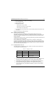
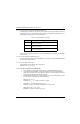
Table 4-3. Feedback Frequency Ranges
Band VCO Feedback Frequency
VHF TX Freq x 2 or
RX Freq + 109.65 MHz
UHF TX Freq or
RX Freq + 109.65 MHz
800 MHz TX Freq / 2 or
(RX Freq - 109.65 MHz) / 2