
Service manual


68P81076C25-C July 1, 2002
Troubleshooting Procedures: Power Amplifier Procedures 4-63
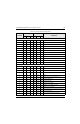
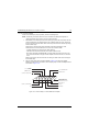
NOTE: The LLA voltages change with different control voltages. An example of LLA voltages with
control voltage equal to 10.0 V and 6 V is shown.
If Q5803 draws no current under normal conditions, then check for short or open input cable, or for
defective parts in the transmit injection filter or matching circuitry between Q5801 and Q5803. If all of
the above check out OK, then replace Q5803.
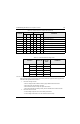
2. Testing Pre-Driver Circuitry.
The pre-driver is a typical class-C stage, except the base is biased with resistors R5809 and
R5806. The necessary conditions for proper operation of this stage are input drive power, and
bias conditions as shown in Table 4-22, above.
NOTE: If it is necessary to replace Q5803, use a hot-air blower to remove and replace the part. It is
important that the replacement device's case be properly soldered to its heatsink. Do so by
flowing a small bead of solder around the rim of the device while it is clamped in the hot-air
soldering device. The base and collector leads must be hand-soldered on the bottom side of
the board.
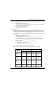
3. Troubleshooting the Driver Stage
- Make sure A+ is at the collector.
- Check for shorts and/or opens in the matching circuitry. Also look for faulty components.
(Cracked parts or parts not properly soldered).
- Measure the DC resistance from base to emitter. It should be less than 1-ohm. If not,
check L5851 and L5852 for proper soldering, and replace if faulty.
- Check the current drain of the driver. It should be around 1.5 to 2.0 A. for 40-Watt
operation. If current drain is low, go to next step.
- Remove L5851 from the board and check the base-emitter and base-collector junction
diode drops. Normal voltage drop should be between 0.4 and 1.0 V. If either junction
reads outside this range, replace the driver device.
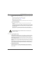
4. Troubleshooting the Final Device
- Make sure A+ is at the final's collector; if not, check for shorts and/or opens. If A+ is
shorted, check C5877 and C5878 first for shorts, by lifting L5878 and measuring the
resistance from collector to ground.
- Check the matching circuitry for shorts and/or opens. Also, check for faulty components.
(Cracked parts or parts not properly soldered.)
- Measure the resistance from base to emitter; it should be less than 1 ohm. If not, check
for proper soldering on L5875, L5876, and L5883; replace faulty component(s).
- Current drain on the final device should be >5 A. for 40-Watt operation. If low current, go
on to the next step.
- Remove L5875 from the board and check the base-emitter and base-collector junction
diode drops. Normal voltage drop should be between 0.4 and 1.0 V. If either junction is
outside this range, replace the final device.
NOTE: The position of capacitors C5875, C5876, C5877, and C5878 is critical to the performance of
the circuit. If they are removed for any reason, they must be re-installed as close to the cap
of the final device as possible.
When replacing either the driver or final device, apply thermal compound on the heatsink
surface. Torque the screws to the correct value; see the ASTRO Digital Spectra and Digital
Spectra Plus Mobile Radios Basic Service Manual (68P81076C20).