® ® Spectra and ® Digital Spectra FM Two-Way Mobile Radios Installation Manual
Foreword The information contained in this manual relates to all Spectra® and ASTRO® Digital Spectra® mobile radios unless otherwise specified. This manual provides information for installation of a Spectra or ASTRO Digital Spectra mobile radio. Safety Information Before operating a Spectra or ASTRO Digital Spectra mobile radio, please read the Motorola “Product Safety and RF Energy Exposure Booklet for Mobile Two-Way Radios Installed in Vehicles or as Fixed Site Control Stations.
Installation Requirements for Compliance with Radio Frequency (RF) Energy Exposure Safety Standards ATTENTION! This radio is intended for use in occupational/controlled conditions, where users have full knowledge of their exposure and can exercise control over their exposure to meet FCC limits. This radio device is NOT authorized for general population, consumer, or any other use. To ensure compliance to RF Energy Safety Standards: • Install only Motorola approved antennas and accessories.
Notes
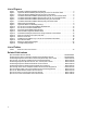
Table of Contents 1 - Description . . . . . . . . . . . . . . . . . . . . . . . . . . . . . . . . . . . . . . . . . . . . . . . . . . . . . . . . . . . . . . . . . . . . . . Introduction. . . . . . . . . . . . . . . . . . . . . . . . . . . . . . . . . . . . . . . . . . . . . . . . . . . . . . . . . . . . . . . . . . . . . . . Radio Model, Control Head, and Version Identification . . . . . . . . . . . . . . . . . . . . . . . . . . . . . . . . . . . . . Radio Dimensions . . . . . . . . . . . . . . . . . . . .
List of Figures Figure 1 Figure 2 Figure 3 Figure 4 Figure 5 Figure 6 Figure 7 Figure 8 Figure 9 Figure 10 Figure 11 Figure 12 Figure 13 Figure 14 Figure 15 Figure 16 Figure 17 Figure 18 Figure 19 Figure 20 Example of a Base/Control Station Configuration . . . . . . . . . . . . . . . . . . . . . . . . . . . . . . . . . . . . . . . . .3 High-Power Radio Installation (Remote) Using A4, A5, A7 or A9 Control Heads . . . . . . . . . . . . . . .5 High-Power Radio Installation (Remote) Using A3 Control Heads . .
1 Description Introduction This manual covers the installation procedures for Spectra® and ASTRO® Digital Spectra radios and accessories required to complete the radio system. The radio system consists of a control head, radio, antenna, microphone, speaker, cabling, and accessories. Radio Model, Control Head, and Version Identification Model charts for the different versions are found in the basic service manual. “Versions” are identified by the model number “suffix.
Radio Dimensions The Spectra and ASTRO Spectra Radios have the following dimensions (H x W x D): 15-watt – 2.0” x 7.1” x 7.5” 20- to 35-watt and 40-watt – 2.0” x 7.1” x 8.6” Base/Control Stations Model charts for the different versions are found in the basic service manual. “Versions” are identified by the model number “suffix.” Although the charts are very similar, there are subtle but very important differences.
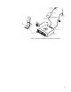
Walloutlet Line Cord with Ground Power Supply Outdoor Antenna Desktop Power Cable Lightning Protector With Quarter Wave Shorting Stub Speaker C C C CCC C CC C C CC CC CC CC CCCC Antenna Cable Antenna Connector CC CC C C Desk Microphone CC C CC CC Radio in Desktop Tray Figure 1 Example of a Base/Control Station Configuration 3
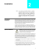
2 Installation NOTE: Planning the Installation In this manual, all information relating to a specific control-head model (A3, A4, A5, A7, or A9) will be applicable to a similar control head in the ASTRO Digital Spectra and Spectra radio families. Examples, A4 control head installation is also applicable to control heads B4, E4, and W4 control heads; A7 control head installation is also applicable to control heads B7, E7, and W7. Figures 2 through 7 show all the possible configurations.
FUSE BATTERY (+) RED LEAD PORT ON BACK OF CONTROL HEAD GRN LEAD FUSE (-) FIREWALL HOLE FUSE BLOCK VIP 1 2 MIC 3 4 7 5 18 19 20 21 ORG LEAD REMOTE MOUNT CONTROL CABLE FUSE HORN RELAY RADIO 10 11 12 13 14 15 16 17 8 23 24 34 35 36 37 38 26 27 28 29 30 31 32 33 43 44 45 46 47 48 49 50 40 41 VIP SECTION PIN OUT LIGHT RELAY PWR Mode MIC CLIP Phon Scan Call Sel Vol SPEAKER 2 3 4 Sts 5 6 Msg 7H/L 8 Mon 9 Dir BUSY Rcl HOME 0 18 SWB + 34 VIP OUT - 3 / DEK STROBE 2 VIP
J2 REAR ACCESSORY CONNECTOR (ASTRO SPECTRA) FUSE BATTERY (+) RED LEAD SPKR NOTE 1 VIP OUT 2 VRS TX/ LO IGNITION NOTE 1 CTS-RS232 SPKR SWB+ EMER HI ANTENNA (-) DIG GND FUSE BLOCK FIREWALL HOLE 8 IGNITION CABLE HORN RELAY ANTENNA CONNECTION PIN-OUT LIGHT RELAY PWR Mode Phon Scan MIC 2 3 4 Sts 5 6 Msg 7H/L 8 Mon 9 Dir XMIT BUSY DIM SPEAKER 1 Sel Call Vol Rcl HOME 0 Del 6 14 5 13 BUS+ 4 3 11 12 VIP OUT 1 NOTE1 2 1 9 10 BUSBUSY MIC HI/RESET/ RTS-RS232 TRUNNION MIC
BATTERY (+) J2 REAR ACCESSORY CONNECTOR (ASTRO SPECTRA) FUSE ANTENNA SPKR NOTE 1 VIP OUT 2 VRS TX/ LO IGNITION NOTE 1 CTS-RS232 SPKR SWB+ EMER HI (-) FUSE BLOCK DIG GND FIREWALL HOLE 8 IGNITION CABLE LIGHT OR HORN RELAY FUSE DC POWER SEE CABLE PIN-OUT HANG-UP BOX 7 15 ANTENNA CONNECTION 6 14 5 13 BUS+ 4 3 2 11 12 VIP OUT 1 NOTE1 BUSBUSY MIC HI/RESET/ RTS-RS232 TRUNNION 1 9 10 PTT/ DISC.
Microphone Hang-up Clip Installation The hang-up clip must be within reach of the operator(s). Measure this distance before actually mounting the bracket. Since the bracket has a positive-detent action, the microphone can mount in any position. The microphone hang-up clip must be grounded. Use the hang-up clip as a template to locate the mounting holes. To avoid interference when removing the microphone, install the flathead screw in the top clip hole.
Remove the fuse from the fuseholder and connect the short red cable with the fuse connection to the positive battery terminal. Cut the long red radio power cable to the proper length and strip the red insulation back 3/4" from the end. Slide the heat-shrink tubing provided with the equipment over the cable. Insert the stripped end into the fuse receptacle (assembly shown in Figure 9), and solder it for a good electrical connection.
! Caution Dash Mount Radio Installation ! Caution To ensure a proper water seal, the jackscrews on the radio cable connector must be tight. If the accessory port on a remote mounted radio is not used, the cover gasket assembly (HLN6233_) must be installed and torqued to 6 to 8 inch-pounds. DO NOT mount the radio on a plastic dashboard without first reinforcing the dashboard; the weight of the radio may crack or break the dashboard.
! DO NOT allow water to stand in recessed areas of vertically mounted radios. Remove any moisture immediately to prevent it from seeping down into the radio. Caution For radios equipped with optional remote mount control heads, see Figure 5. For radios equipped with remote handheld control heads, see Figure 7. Choose a mounting location for the radio, considering accessibility, and control and antenna cable lengths. NOTE: For optimum performance, orient the mounting trunnion as shown in Figures 5 and 7.
Remote A4, A5, A7, and A9 Model Control Head Installation The recommended mounting surfaces for the control unit are under the dashboard, on the transmission hump, or on the center console. Figure 10 shows an example of the A4, A5, and A7 control heads. Figure 12 shows how the bracket, control head, and cables should be installed for the A9 model control head. NOTE: For Control Head Models A4, A5, and A7 only: To seal the control head and meet U. S.
IMPORTANT USE A METAL BACKING PLATE (NOT SUPPLIED) IF MOUNTING TRUNNION ON A PLASTIC DASHBOARD DRILL FOUR 5/32" HOLES IN DASHBOARD DASHBOARD TRUNNION 03-00136756 USE FOUR MOUNTING SCREWS ON ALL INSTALLATIONS ADJUST THE CONTROL HEAD TO DESIRED ANGLE AND SECURE WITH WING SCREWS VIP CONNECTOR TO RADIO ORANGE AND GREEN LEADS TO MICROPHONE TO SPEAKER MAEPF-21453-O Figure 10 A4, A5, and A7 Control Head Installation Exploded View VIP CONNECTOR PROTECTIVE COVER MIC CONNECTOR PROTECTIVE COVER CONTROL CAB
IMPORTANT USE A METAL BACKING PLATE (NOT SUPPLIED) IF MOUNTING TRUNNION ON A PLASTIC DASHBOARD DRILL FOUR 5/32" HOLES IN DASHBOARD DASHBOARD TRUNNION 03-00136756 USE FOUR MOUNTING SCREWS ON ALL INSTALLATIONS ADJUST THE CONTROL HEAD TO DESIRED ANGLE AND SECURE WITH WING SCREWS VIP CONNECTOR TO RADIO ORANGE AND GREEN LEADS TO SPEAKER MAEPF-21373-0 TO MICROPHONE TECHNICAL PUBLICATIONS DEPT. DESCRIPTION A9 Control Head Installation DWG. NO.
Table 1 Radio Functions Connections Conductor Connected to battery Green Orange Green X X X Connected to ignition switch Ignition switch controls No ignition switch control Orange Green Orange X See Note X Transmitter ignition switch controlled Complete radio ignition switch controlled In any application, trim and strip wires. Crimp on ring lug for battery connections. For ignition switch connections, crimp on ring or spade lug (whichever is required).
• Temporarily, install the fuse (both are 3-amp), into the fuse clips onto both sides of the fuse. Slide the spring over the remaining loose end of the wire. The spring should be followed by the plastic insulator fuseholder oriented as shown in Figure 10. Slide the plastic insulator fuse holder together, by first making sure the spring slips inside the plastic insulator fuseholder cap. Now, twist the fuseholders until they lock together.
Receiver Control Power Lead (Green) Connect the green lead to the positive battery terminal (recommended) or the ignition switch (see Figure 8). When alternator whine or interference is a problem, Figure 13 shows an alternate power control isolation method of wiring the green lead.
BEFORE INSTALLING AN ANTENNA ON THE TRUNK LID, - Be sure that the distance from the antenna location on the trunk lid will be at least 85 cm (33 inches) from the front surface of the rear seat-back to assure compliance with RF Energy Safety standards. - Ensure that the trunk lid is grounded by connecting grounding straps between the trunk lid and the vehicle chassis. NOTE: If these conditions cannot be satisfied, then mount the antenna on the roof top. 4.
Antenna Connection To ensure a secure connection of an antenna cable's mini-UHF plug to a radio's mini-UHF jack, their interlocking features must be properly engaged. If they are not properly engaged, the system will loosen. NOTE: Applying excessive force with a tool can cause damage to the antenna or the connector (e.g., stripping threads, deforming the collar or connector, or causing the connector to twist in the housing opening and break).
INSTALL PHONE BUTTON HERE PWR Mode Phon Scan Vol 1 2 3 4 Sts 5 6 Msg 7H/L 8 Mon 9 Dir XMIT BUSY DIM MIC Sel Rcl HOME 0 Del MAEPF-21423-O Figure 17 Installing the Phone Button Key on A4, A5, and A7 Model Control Heads Options and Accessories Installation for A4, A5, A7, and A9 Model Control Heads The vehicle interface port (VIP) allows the control head to operate outside circuits and to receive inputs from outside the control head.
Emergency Pushbutton, Footswitch, Horn Relay, and Light Relay Installation Perform the following installation procedure: 1. Select an appropriate place to mount the option or accessory hardware. 2. Connect male-pin control leads (wires) to the VIP connector in the appropriate location (see Output/Input Connections tables above). Figure 18 shows how wires are plugged into the connector and how to use an extraction tool to remove wires. 3.
All ASTRO Digital Spectra radios and Spectra radios have accessory connector pins 2 and 8 connected together to allow the radio to power down. Opening this connection by C a u t i o n REMOVING the accessory connector, or otherwise failing to maintain a normally closed path, could, if left unchecked, drain the vehicle battery, and possibly cause transmissions to occur. ! To install an option or accessory perform the following installation procedure: 1.
2. Lights Relay–Connect the relay across the headlamp ON/OFF switch, typically found in the steering column. Open the accessory cable connector and connect the two control wires (male pins) into locations 3 and 4 of the accessory connector. SPST N.O. RELAY CONNECT ACROSS HORN RING SWITCH VIP OUT 1 PIN 12 12V COIL SWB+ SPST N.O.
Connecting Cables Perform the following if it has not been previously done: 1. For all models except A3, remove the control head from its mounting trunnion. Plug the radio’s control cable into the proper location on the back of the control head. (See Figures 10 and 12.) The connectors “click” when snapped into place.
REPLACEMENT PARTS ORDERING ORDERING INFORMATION When ordering replacement parts or equipment information, the complete identification number should be included. This applies to all components, kits, and chassis. If the component part number is not known, the order should include the number of the chassis or kit of which it is a part, and sufficient description of the desired component to identify it.
*6881070C85* *6881070C85* 68P81070C85-D Motorola 8000 West Sunrise Boulevard Fort Lauderdale, Florida 33322