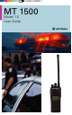
COLOR CHORDS 7 MT 1500 Model 1.
MT1500 1.5 UG.book Page 1 Thursday, May 8, 2008 11:17 AM MT 1500 Digital Portable Radio, Model 1.5 Quick Reference Card Product Safety and RF Exposure Compliance Before using this product, read the operating instructions for safe usage contained in the Product Safety and RF C a u t i o n Exposure booklet enclosed with your radio. ! ATTENTION! This radio is restricted to occupational use only to satisfy FCC RF energy exposure requirements.
MT1500 1.5 UG.book Page 2 Thursday, May 8, 2008 11:17 AM Answer a Phone Call 1 Phone-like ringing, LED blinks GREEN, PHONE CALL and m are displayed. 2 Press Call Response button. 3 Press PTT button to talk; release to listen. 4 Press Call Response button again to hang up. Display Status Symbols m p Call Received. Receiving an individual call. View Mode. The radio is in the view mode. s Received Signal Strength Indication (RSSI). Received signal strength for the current site (trunking only).
MT1500 1.5 UG.book Page i Thursday, May 8, 2008 11:17 AM This declaration is applicable to your radio only if your radio is labeled with the FCC logo shown below. DECLARATION OF CONFORMITY Per FCC CFR 47 Part 2 Section 2.1077(a) Responsible Party Name: Motorola, Inc. Address: 1301 E. Algonquin Rd, Schaumburg, IL 60196-1078 USA Phone Number: 1-800-927-2744 Hereby declares that the product: Model Name: MT 1500 conforms to the following regulations: FCC Part 15, subpart B, section 15.107(a), 15.
MT1500 1.5 UG.book Page ii Thursday, May 8, 2008 11:17 AM Product Safety and RF Exposure Compliance Before using this product, read the operating instructions for safe usage contained in the Product C a u t i o n Safety and RF Exposure booklet enclosed with your radio. ! ATTENTION! This radio is restricted to occupational use only to satisfy FCC RF energy exposure requirements.
MT1500 1.5 UG.book Page iii Thursday, May 8, 2008 11:17 AM Documentation Copyrights No duplication or distribution of this document or any portion thereof shall take place without the express written permission of Motorola. No part of this manual may be reproduced, distributed, or transmitted in any form or by any means, electronic or mechanical, for any purpose without the express written permission of Motorola.
MT1500 1.5 UG.book Page iv Thursday, May 8, 2008 11:17 AM Notes iv MT 1500 Model 1.
MT1500 1.5 UG.book Page v Thursday, May 8, 2008 11:17 AM Contents Declaration of Conformity ................................................................... i Product Safety and RF Exposure Compliance ................................. ii Computer Software Copyrights ......................................................... ii Documentation Copyrights ................................................................iii Disclaimer ............................................................................
MT1500 1.5 UG.book Page vi Thursday, May 8, 2008 11:17 AM Common Radio Features............................................ 25 Selectable Power Level ................................................................... 25 Conventional Squelch Options ........................................................ 25 Analog Squelch ........................................................................ 25 PL Defeat ........................................................................................
MT1500 1.5 UG.book Page vii Thursday, May 8, 2008 11:17 AM Battery Life ............................................................................... 42 Charging the Battery ................................................................. 43 Battery Recycling and Disposal ...................................................... 44 Antenna ........................................................................................... 45 Radio Operating Frequencies ..............................................
MT1500 1.5 UG.book Page viii Thursday, May 8, 2008 11:17 AM Notes viii MT 1500 Model 1.
MT1500 1.5 UG.book Page 1 Thursday, May 8, 2008 11:17 AM General Radio Operation Notations Used in This Manual You will notice the use of WARNING, CAUTION, and Note notations throughout this manual. These notations are used to emphasize that safety hazards exist and that care must be taken or observed. ! An operational procedure, practice, condition, etc. exists which may result in injury or death if not carefully observed. ! An operational procedure, practice, condition, etc.
MT1500 1.5 UG.book Page 2 Thursday, May 8, 2008 11:17 AM General Radio Operation MT 1500 Model 1.
MT1500 1.5 UG.book Page 3 Thursday, May 8, 2008 11:17 AM General Radio Operation Physical Features of the MT 1500 Model 1.
MT1500 1.5 UG.book Page 4 Thursday, May 8, 2008 11:17 AM General Radio Operation Programmable Features The programmable controls on your radio can be programmed by a qualified technician to operate certain software-activated features. The features that can be assigned to these controls, and the page numbers where these features can be found, are listed below.
MT1500 1.5 UG.book Page 5 Thursday, May 8, 2008 11:17 AM General Radio Operation Display MAEPF-27252-O This figure is typical of what you see on your radio. The 64 x 96 pixel liquid crystal display (LCD) shows radio status, text, and menu entries. Backlight If poor light conditions make the display difficult to read, turn on the radio’s backlight by pressing the Light button.
MT1500 1.5 UG.book Page 6 Thursday, May 8, 2008 11:17 AM General Radio Operation Status Symbols The top two rows in the display contain symbols indicating the radio’s status. Table 2: Status Symbols Symbol Indication Page m Call Received. Blinks when a Private Call is received. 34 p View Mode. View a list. 31 Received Signal Strength Indication (RSSI). The received signal strength for the current site. Trunked only. The more stripes in the symbol, the stronger the received signal.
MT1500 1.5 UG.book Page 7 Thursday, May 8, 2008 11:17 AM General Radio Operation Light Emitting Diode (LED) Indicators Table 3: LED Indicators This LED Color: RED (Illuminated) Indicates: Transmitting • Channel Busy RED (Blinking) OR • Low Battery (lights while transmitting) GREEN (Blinking) Receiving Individual Call Alert Tones Your radio uses alert tones to inform you of radio conditions.
MT1500 1.5 UG.book Page 8 Thursday, May 8, 2008 11:17 AM General Radio Operation Table 4: Alert Tones (Continued) You hear: Long, Low-Pitched Tone A Group of Low-Pitched Tones (Busy Tone) Tone Name Invalid Mode when the radio is set to an unprogrammed channel. Individual Call Warning Tone when the radio is in Individual Call without any activity for more than 6 seconds. Busy when the system is busy. Valid Key-Press when the correct key is pressed.
MT1500 1.5 UG.book Page 9 Thursday, May 8, 2008 11:17 AM General Radio Operation Table 4: Alert Tones (Continued) You hear: Tone Name Failsoft Heard: when the trunking system fails. when the voice channel is Automatic Call Back available from the previous request. A Group of MediumPitched Tones Talk Permit (when pressing the PTT button) verifies the system is accepting transmissions. Console Acknowledge when a status, emergency alarm, or reprogram request acknowledgment is received.
MT1500 1.5 UG.book Page 10 Thursday, May 8, 2008 11:17 AM General Radio Operation Standard Accessories Battery ! WARNING To avoid a possible explosion: • DO NOT replace the battery in any area labeled “hazardous atmosphere”. • DO NOT discard batteries in a fire. Charge the Battery The Motorola approved battery shipped with your radio is uncharged. Prior to using a new battery, charge it for a minimum of 16 hours to ensure optimum capacity and performance.
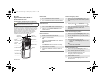
MT1500 1.5 UG.book Page 11 Thursday, May 8, 2008 11:17 AM General Radio Operation Attach the Battery 1 With the radio off, fit the three extensions at the bottom of the battery into the bottom slots on the radio. 2 Press both sides at the top of the battery against the radio until both latches click into place. Remove the Battery 1 With the radio off, slide down the latches on the sides of the battery. 2 Pull the top of the battery away from the radio. MT 1500 Model 1.
MT1500 1.5 UG.book Page 12 Thursday, May 8, 2008 11:17 AM General Radio Operation Smart Battery Condition This feature allows you to view the condition of your Smart Battery. 1 Press the Smart Battery button. CAPACITY INIT EST CHGS Note: If a Smart Battery is not powering your radio: SMART BATT DATA NOT AVAILABLE 2 12 Press the Smart Battery button again to exit.
MT1500 1.5 UG.book Page 13 Thursday, May 8, 2008 11:17 AM General Radio Operation Antenna For information regarding other available antennas, see page 47. Attach the Antenna 1 With the radio off, turn the antenna clockwise to attach it. Remove the Antenna 1 With the radio off, turn the antenna counterclockwise to remove it. MT 1500 Model 1.
MT1500 1.5 UG.book Page 14 Thursday, May 8, 2008 11:17 AM General Radio Operation Belt Clip Attach the Belt Clip 1 Align the grooves of the belt clip with those of the battery. 2 Press the belt clip downward until you hear a “click.” Remove the Belt Clip 1 Use a flat-bladed screwdriver to press the belt clip tab away from the battery. 2 Slide the belt clip upward to remove it.
MT1500 1.5 UG.book Page 15 Thursday, May 8, 2008 11:17 AM General Radio Operation Universal Connector Cover The universal connector cover is located on the antenna side of the radio. It is used to connect certain accessories to the radio. Note: To prevent damage to the connector, shield it with the connector cover when not in use. Remove the Connector Cover 1 Insert a flat-bladed screwdriver into the area between the bottom of the cover and the slot below the connector.
MT1500 1.5 UG.book Page 16 Thursday, May 8, 2008 11:17 AM General Radio Operation Remote Speaker Microphone Adapter The Remote Speaker Microphone (RSM) adapter is located on the back of the radio, just above the battery. It must be used to connect the RSM accessories (see page 50) to the radio. If the RSM is not used, the adapter should be removed. Remove the Adapter 1 Lift the larger side (below the antenna port) of the adapter away from the radio using your finger.
MT1500 1.5 UG.book Page 17 Thursday, May 8, 2008 11:17 AM General Radio Operation Radio On and Off Turn the Radio On Turn the On/Off/Volume Control knob clockwise. • • If the power-up test is successful, you will briefly see SELF TEST and then the home display. If the power-up test is unsuccessful, you will see ERROR XX/YY. (XX/YY is an alphanumeric code.) Turn off the radio, check the battery, and turn the radio on again.
MT1500 1.5 UG.book Page 18 Thursday, May 8, 2008 11:17 AM General Radio Operation Zones and Channels A zone is a grouping of channels. A channel is a group of radio characteristics, such as transmit/receive frequency pairs. Before you use your radio to receive or send messages, you should select the zone. Select a Zone 1 If a control on your radio has been preprogrammed as the Zone Switch, move the Zone Switch to the position for the zone you want.
MT1500 1.5 UG.book Page 19 Thursday, May 8, 2008 11:17 AM General Radio Operation Mode Select Button This feature lets you program the current zone and channel to a Mode Select button with a long press on the Mode Select button. After the buttons are programmed, you can return to the preprogrammed zone and channel with a short press on the programmed Mode Select button. The buttons that are assigned for this feature are labeled in the following picture.
MT1500 1.5 UG.book Page 20 Thursday, May 8, 2008 11:17 AM General Radio Operation Receive / Transmit Radio users who switch from analog to digital radios often assume that the lack of static on a digital channel is an indication that the radio is not working properly. This is not the case. Digital technology quiets the transmission by removing the “noise” from the signal and allowing only the clear voice or data information to be heard.
MT1500 1.5 UG.book Page 21 Thursday, May 8, 2008 11:17 AM General Radio Operation Use the Preprogrammed Volume Set Button 1 Turn the radio on and select the desired zone and channel. See Turn the Radio On, page 17 and Zones and Channels, page 18. 2 Press and hold the Volume Set button to hear the volume set tone. 3 Release the Volume Set button. 4 Adjust the Volume Control Knob if necessary. 5 Press and hold the PTT button to transmit. LED lights RED while transmitting.
MT1500 1.5 UG.book Page 22 Thursday, May 8, 2008 11:17 AM General Radio Operation Use the Preprogrammed Monitor Button 1 Turn the radio on and select the desired zone and channel. 2 Press the Monitor button and listen for activity. (See the following Conventional Mode Operation.) 3 Adjust the Volume Control knob if necessary. 4 Press and hold the PTT button to transmit. The LED lights RED while transmitting. 5 Release the PTT button to receive (listen).
MT1500 1.5 UG.book Page 23 Thursday, May 8, 2008 11:17 AM General Radio Operation Conventional Mode Operation Your radio may be programmed to receive Private-Line® (PL) calls. 1 Momentarily press the Monitor button to listen for activity. 2 Press and hold the Monitor button to set continuous monitor operation. (The duration of the button press is programmable.) 3 C Press the Monitor button again, or the PTT button, to return to the original squelch setting.
MT1500 1.5 UG.
MT1500 1.5 UG.book Page 25 Thursday, May 8, 2008 11:17 AM Common Radio Features Selectable Power Level This feature lets you select the power level at which your radio will transmit. The radio will always turn on to the preprogrammed default setting. This feature must be programmed by a qualified radio technician. • Select LOW for a shorter transmitting distance and to conserve power. • Select HIGH for longer transmitting distance. 1 Rotate the TX Power Level switch. The power level is set to low.
MT1500 1.5 UG.book Page 26 Thursday, May 8, 2008 11:17 AM Common Radio Features PL Defeat With this feature, you can override any coded squelch (DPL, PL, or network ID) that might be programmed to a channel. Place the preprogrammed PL Defeat switch in the PL Defeat position. You can now hear any activity on the channel. The radio is muted if no activity is present. When this feature is active, the Carrier Squelch status indicator (C) will be displayed.
MT1500 1.5 UG.book Page 27 Thursday, May 8, 2008 11:17 AM Common Radio Features Emergency If the top (orange) button is programmed to send an emergency signal, then this signal overrides any other communication over the selected channel. Your radio can be programmed for the following: • Emergency Alarm • Emergency Alarm with Emergency Call • Silent Emergency Alarm • Emergency Call Consult a qualified radio technician for emergency programming of your radio.
MT1500 1.5 UG.book Page 28 Thursday, May 8, 2008 11:17 AM Common Radio Features 2 When you receive the dispatcher’s acknowledgment, you see ACK RECEIVED, four tones sound, the alarm ends, and the radio exits the emergency mode. If no acknowledgement is received, you see NO ACKNOWLDG, the alarm ends, and the radio exits the emergency mode.
MT1500 1.5 UG.book Page 29 Thursday, May 8, 2008 11:17 AM Common Radio Features Send a Silent Emergency Alarm 1 With your radio turned on, press the Emergency button. The display does not change, the LED does not light, and you hear no tones. • Display does not change • LED does not light • No tones Note: To exit emergency at any time, press and hold the Emergency button for about a second.
MT1500 1.5 UG.book Page 30 Thursday, May 8, 2008 11:17 AM Common Radio Features 2 Press and hold the PTT button and announce your emergency into the microphone. 3 Release the PTT button to end the transmission and wait for a response from the dispatcher. 4 Press and hold the Emergency button for about a second to exit emergency.
MT1500 1.5 UG.book Page 31 Thursday, May 8, 2008 11:17 AM Common Radio Features Emergency Keep-Alive With Emergency Keep-Alive enabled, if the radio is in the Emergency state, you cannot turn off the radio by using the On/Off Volume Control knob. With Keep-Alive, the radio will only exit the Emergency state using one of the ways mentioned in the previous sections (Emergency Alarm, Silent Emergency Alarm, or Emergency Call).
MT1500 1.5 UG.book Page 32 Thursday, May 8, 2008 11:17 AM Common Radio Features Scan List Empty If the scan list has no members, EMPTY LIST is displayed. EMPTY LIST EMPTY LIST can be changed by turning scan off, or a qualified technician adds members to the scan list. Delete a Nuisance Channel When the radio scans to a channel that you do not wish to hear (nuisance channel), you can temporarily delete the channel from the scan list.
MT1500 1.5 UG.book Page 33 Thursday, May 8, 2008 11:17 AM Common Radio Features Conventional Scan Only Make a Dynamic Priority Change While the radio is scanning, the dynamic priority change feature lets you temporarily change any channel in a scan list (except the priority-one channel) to the priority-two channel. The replaced priority-two channel becomes a non-priority channel. This change remains in effect until scan is turned off, then scanning reverts back to the preprogrammed state.
MT1500 1.5 UG.book Page 34 Thursday, May 8, 2008 11:17 AM Common Radio Features Telephone Calls (Trunking Only) Use your radio to receive standard phone calls. A landline phone can be used to call a radio. Answer a Phone Call 1 When a phone call is received, you hear a telephone-type ringing, the LED blinks Green, the call-received symbol (m) blinks, and PHONE CALL is displayed. 2 Press the Call Response button within 20 seconds after the call indicators begin.
MT1500 1.5 UG.book Page 35 Thursday, May 8, 2008 11:17 AM Common Radio Features Private Calls (Trunking Only) These one-to-one calls between two radios are not heard by others in the current talkgroup. The calling radio automatically verifies that the receiving radio is active on the system and that it can display the caller’s ID. Answer a Private Call 1 2 When a private call is received, you hear two alert tones, the LED blinks Green, the call-received symbol (m) blinks, and CALL RECEIVD is displayed.
MT1500 1.5 UG.book Page 36 Thursday, May 8, 2008 11:17 AM Common Radio Features Call Alert Paging Call Alert allows your radio to work like a pager. Answer a Call Alert Page 1 2 When a Call Alert Page is received, you hear four repeating alert tones, the LED blinks Green the call-received symbol (m) blinks, and PAGE RECEIVED is displayed. m PAGE RECEIVD • Four repeating alert tones • Blinking Green LED Press and hold the PTT button to talk, release it to listen.
MT1500 1.5 UG.book Page 37 Thursday, May 8, 2008 11:17 AM Special Radio Features PTT ID Transmit Your radio’s ID number is automatically sent every time the PTT button is pressed. This is a per-channel feature. For digital voice transmissions, your radio’s ID is sent continuously during the voice message. Trunking System Controls Failsoft The failsoft system ensures continuous radio communications during a trunked system failure.
MT1500 1.5 UG.book Page 38 Thursday, May 8, 2008 11:17 AM Special Radio Features Out-of-Range If you go out of the range of the system, and can no longer lock onto a control channel: The display shows OUT OF RANGE and the currently selected zone/channel combination, and/ or you hear a low-pitched tone.
MT1500 1.5 UG.book Page 39 Thursday, May 8, 2008 11:17 AM Special Radio Features Site View and Change View the Current Site Momentarily press the preprogrammed Site Search button. The display shows either the number of the current site and its corresponding Received Signal Strength Indicator (RSSI) symbol (s). (See Table 2 on page 6.) s SITE 2 OR If the radio is scanning for a new site, the display momentarily shows SCANING SITE.
MT1500 1.5 UG.
MT1500 1.5 UG.book Page 41 Thursday, May 8, 2008 11:17 AM Helpful Tips Radio Care Cleaning To clean the external surfaces of your radio: 1 Combine one teaspoon of mild dishwashing detergent to one gallon of water (0.5% solution). 2 Apply the solution sparingly with a stiff, non-metallic, short-bristled brush, making sure excess detergent does not get entrapped near the connectors, controls or crevices. Dry the radio thoroughly with a soft, lint-free cloth.
MT1500 1.5 UG.book Page 42 Thursday, May 8, 2008 11:17 AM Helpful Tips Service Proper repair and maintenance procedures will assure efficient operation and long life for this product. A Motorola maintenance agreement will provide expert service to keep this and all other communication equipment in perfect operating condition. A nationwide service organization is provided by Motorola to support maintenance services.
MT1500 1.5 UG.book Page 43 Thursday, May 8, 2008 11:17 AM Helpful Tips Charging the Battery Motorola batteries are designed specifically to be used with a Motorola charger and vice-versa. Charging in non-Motorola equipment may lead to battery damage and void the battery warranty. Motorola-authorized battery chargers may not charge batteries other than the ones listed on page 48. The battery should be at about 77°F (25°C) (room temperature), whenever possible.
MT1500 1.5 UG.book Page 44 Thursday, May 8, 2008 11:17 AM Helpful Tips Gauge shows: b j k l If the battery’s charge is: 71% to 100% full 41% to 70% 11% to 40% 10% or less (at 10%, the gauge begins blinking) Replace the battery with a fully charged one when the fuel gauge shows the lowest level. Battery Recycling and Disposal Nickel-cadmium (NiCd) rechargeable batteries can be recycled. However, recycling facilities may not be available in all areas. Under various U.S.
MT1500 1.5 UG.book Page 45 Thursday, May 8, 2008 11:17 AM Helpful Tips Antenna Radio Operating Frequencies Before installing the antenna, make sure it matches your radio’s operating frequency. Antennas are frequency sensitive and are color coded according to their frequency range. The color code indicator is located in the center of the antenna’s base. color The following antenna types are compatible with your radio: Antenna Type Approx. Length in. Insulator Color Code mm.
MT1500 1.5 UG.
MT1500 1.5 UG.book Page 47 Thursday, May 8, 2008 11:17 AM Accessories Accessories Motorola provides the following approved accessories to improve the productivity of your MT 1500 portable two-way radio. For a list of Motorola-approved antennas, batteries, and other accessories, visit the following web site which lists approved accessories: http://www.motorola.com/governmentandenterprise/ Antennas NAD6563 VHF whip (136–174 MHz) NAD6566 VHF (136–150.8 MHz) NAD6567 VHF (150.
MT1500 1.5 UG.
MT1500 1.5 UG.
MT1500 1.5 UG.book Page 50 Thursday, May 8, 2008 11:17 AM Accessories Microphones, Remote Speaker NMN6191 Remote speaker mic, noise-canceling (includes 6.0-ft. coiled cord assembly, 3.
MT1500 1.5 UG.
MT1500 1.5 UG.
MT1500 1.5 UG.book Page 53 Thursday, May 8, 2008 11:17 AM Appendix: Maritime Radio Use in the VHF Frequency Range Appendix: Maritime Radio Use in the VHF Frequency Range Special Channel Assignments Emergency Channel If you are in imminent and grave danger at sea and require emergency assistance, use VHF Channel 16 to send a distress call to nearby vessels and the United States Coast Guard. Transmit the following information, in this order: 1 “MAYDAY, MAYDAY, MAYDAY.
MT1500 1.5 UG.book Page 54 Thursday, May 8, 2008 11:17 AM Appendix: Maritime Radio Use in the VHF Frequency Range 11 If you do not receive an immediate response, remain by the radio and repeat the transmission at intervals until you receive a response. Be prepared to follow any instructions given to you. Non-Commercial Call Channel For non-commercial transmissions, such as fishing reports, rendezvous arrangements, repair scheduling, or berthing information, use VHF Channel 9.
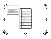
MT1500 1.5 UG.book Page 55 Thursday, May 8, 2008 11:17 AM Appendix: Maritime Radio Use in the VHF Frequency Range Table A-1: VHF Marine Channel List (Continued) Frequency (MHz) Channel Number Transmit Receive 5 156.250 160.850 6 156.300 – 7 156.350 160.950 8 156.400 – 9 156.450 156.450 10 156.500 156.500 11 156.550 156.550 12 156.600 156.600 13** 156.650 156.650 14 156.700 156.700 15** 156.750 156.750 16 156.800 156.800 17** 156.850 156.850 18 156.900 161.
MT1500 1.5 UG.book Page 56 Thursday, May 8, 2008 11:17 AM Appendix: Maritime Radio Use in the VHF Frequency Range Table A-1: VHF Marine Channel List (Continued) Frequency (MHz) Channel Number Transmit Receive * 156.225 160.825 65 156.275 160.875 66 156.325 160.925 67** 156.375 156.375 68 156.425 156.425 69 156.475 156.475 71 156.575 156.575 72 156.625 – 73 156.675 156.675 74 156.725 156.725 75 *** *** 76 *** *** 77** 156.875 – 78 156.925 161.525 79 156.
MT1500 1.5 UG.book Page 57 Thursday, May 8, 2008 11:17 AM Glossary This is a list of specialized terms used in this manual. ACK Acknowledgment of communication. Active Channel A channel that has traffic on it. Analog Signal An RF signal that has a continuous nature rather than a pulsed or discrete nature. ASTRO 25 Trunking Motorola standard for wireless digital trunked communications. ASTRO Conventional Motorola standard for wireless analog or digital conventional communications.
MT1500 1.5 UG.book Page 58 Thursday, May 8, 2008 11:17 AM Glossary Digital Private Line (DPL) A type of coded squelch using data bursts. Similar to PL except a digital code is used instead of a tone. Digital Signal An RF signal that has a pulsed, or discrete nature, rather than a continuous nature. Dispatcher An individual who has radio system management duties.
MT1500 1.5 UG.book Page 59 Thursday, May 8, 2008 11:17 AM Glossary Network Access Code Network Access Code (NAC) operates on digital channels to reduce voice channel interference between adjacent systems and sites. NiCd Nickel Cadmium. NiMH Nickel Metal Hydride. Non-Tactical/Revert The user will talk on a preprogrammed emergency channel. The emergency alarm is sent on this same channel. Page A one-way alert, with audio and/or display messages.
MT1500 1.5 UG.book Page 60 Thursday, May 8, 2008 11:17 AM Glossary Repeater A conventional radio feature, where you talk through a receive/transmit facility (repeater), that re-transmits received signals in order to improve communications range and coverage. Selective Switch Any digital P25 traffic having the correct Network Access Code and the correct talkgroup.
MT1500 1.5 UG.book Page 61 Thursday, May 8, 2008 11:17 AM Commercial Warranty Limited Warranty MOTOROLA COMMUNICATION PRODUCTS I. WHAT THIS WARRANTY COVERS AND FOR HOW LONG: MOTOROLA INC.
MT1500 1.5 UG.book Page 62 Thursday, May 8, 2008 11:17 AM Commercial Warranty MOTOROLA cannot be responsible in any way for any ancillary equipment not furnished by MOTOROLA which is attached to or used in connection with the Product, or for operation of the Product with any ancillary equipment, and all such equipment is expressly excluded from this warranty.
MT1500 1.5 UG.book Page 63 Thursday, May 8, 2008 11:17 AM Commercial Warranty IV. HOW TO GET WARRANTY SERVICE: You must provide proof of purchase (bearing the date of purchase and Product item serial number) in order to receive warranty service and, also, deliver or send the Product item, transportation and insurance prepaid, to an authorized warranty service location. Warranty service will be provided by Motorola through one of its authorized warranty service locations.
MT1500 1.5 UG.book Page 64 Thursday, May 8, 2008 11:17 AM Commercial Warranty G) Rechargeable batteries if: • any of the seals on the battery enclosure of cells are broken or show evidence of tampering. • the damage or defect is caused by charging or using the battery in equipment or service other than the Product for which it is specified. H) Freight costs to the repair depot.
MT1500 1.5 UG.book Page 65 Thursday, May 8, 2008 11:17 AM Commercial Warranty will permit MOTOROLA, at its option and expense, either to procure for such purchaser the right to continue using the Product or parts or to replace or modify the same so that it becomes non-infringing or to grant such purchaser a credit for the Product or parts as depreciated and accept its return. The depreciation will be an equal amount per year over the lifetime of the Product or parts as established by MOTOROLA.
MT1500 1.5 UG.
MT1500 1.5 UG.book Page 67 Thursday, May 8, 2008 11:17 AM Index A accessories antennas .................................47 batteries ..................................48 belt clips ..................................48 body-worn ...............................48 carry accessories ....................48 chargers ..................................49 Commport integrated microphone/receivers ............50 earpieces .................................51 headsets ..................................
MT1500 1.5 UG.book Page 68 Thursday, May 8, 2008 11:17 AM Index PL defeat .....................................26 programmable features .................4 PTT ID .........................................37 R radio ID number ..........................37 receive / transmit use the preprogrammed monitor button ........................22 use the preprogrammed volume set button ...................21 without using the volume set and monitor buttons ...............20 remote speaker microphone adapter ..........
6871199L01_BCKCVR_D.pdf 4/25/2008 7:08:44 PM C M Y CM MY CY CMY K Motorola, Inc. 1301 E. Algonquin Rd. Schaumburg, IL60196-1078, USA. MOTOROLA, the Stylized M Logo, ASTRO, and SmartZone are registered in the U.S. Patent & Trademark Office. All other product or service names are the property of their respective owners. © 2007, 2008 by Motorola, Inc. All rights reserved. Printed in U.S.A.