
Computer Accessories User Manual


Controls, Indicators, and Connectors On−Board Connectors
66 PENT/ATCA−717
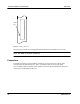
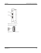
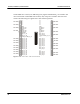
On the PMC sites 1 and 4, two Ethernet ports (signals named ETH*_) are routed to the
on−board switch. On the PMC sites 2 and 3, only one port is routed to the on−board
switch. The following two figures show the connector pinouts.
aaa
1
3
5
7
9
11
13
15
17
19
21
23
25
27
29
31
33
35
37
39
41
43
45
47
49
51
53
55
57
59
61
63
2
4
6
8
10
12
14
16
18
20
22
24
26
28
30
32
34
36
38
40
42
44
46
48
50
52
54
56
58
60
62
64
n.c.
n.c.
n.c.
n.c.
n.c.
GND
ETHB_DC+
ETHB_DC−
GND
ETHB_DD+
ETHB_DD−
n.c.
PMC_IO_26
PMC_IO_28
CLK8_A or PMC_IO_30
n.c.
PMC_IO_34
PMC_IO_36
PMC_IO_38
PMC_IO_40
PMC_IO_42
PMC_IO_44
PMC_IO_46
PMC_IO_48
n.c.
PMC_IO_52
PMC_IO_54
n.c.
PMC_IO_58
PMC_IO_60
PMC_IO_62
PMC_IO_64
n.c.
n.c.
n.c.
n.c.
n.c.
GND
ETHB_DA+
ETHB_DA−
GND
ETHB_DB+
ETHB_DB−
NETREF
PMC_IO_25
n.c.
PMC_IO_29
CLK8_B or PMC_IO_31
PMC_IO_33
PMC_IO_35
PMC_IO_37
PMC_IO_39
PMC_IO_41
PMC_IO_43
PMC_IO_45
PMC_IO_47
PMC_IO_49
PMC_IO_51
PMC_IO_53
PMC_IO_55
PMC_IO_57
PMC_IO_59
PMC_IO_61
PMC_IO_63
}
Diff. Pair
}
Diff. Pair
}
Diff. Pair
}
Diff. Pair
}
Diff. Pair
}
Diff. Pair
}
Diff. Pair
}
Diff. Pair
}
Diff. Pair
}
Diff. Pair
}
Diff. Pair
}
Diff. Pair
{
Diff. Pair
{
Diff. Pair
{
Diff. Pair
{
Diff. Pair
{
Diff. Pair
{
Diff. Pair
{
Diff. Pair
{
Diff. Pair
{
Diff. Pair
{
Diff. Pair
{
Diff. Pair
{
Diff. Pair
Figure 13: PMC Sites 1 and 4 − Pn4 Connector Pinout