
user manual


Connectors
http://www.motorola.com/computer/literature 5-39
5
9 GND Drive
common
10 MTR0 Motor enable
output
11 GND Drive
common
12 DS1 Drive select 1
13 GND Drive
common
14 DS0 Drive select 0
15 GND Drive
common
16 MTR1 Motor enable
output
17 GND Drive
common
18 DIR Controls
direction of the
floppy disk drive
head during seek
operation
19 GND Drive
common
20 STEP Supplies step
pulses to move
head during seek
operations
21 GND Drive
common
22 WDATA Writes serial data
to disk drive
23 GND Drive
common
24 WGATE Enables head of
disk drive to
write to disk
25 GND Drive
common
26 TR0 Head of floppy
disk drive is at
track 0
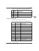
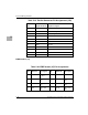
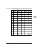
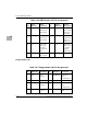
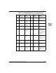
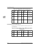
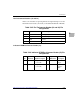
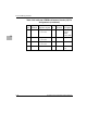
Table 5-21. Floppy Header (J9) Pin Assignments
Pin
Signal
Mnemonic
Signal
Description Pin
Signal
Mnemonic
Signal
Description