
user manual

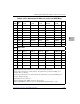
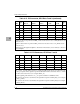

Peripheral Signal Connectors (SIG1, SIG2, SIG3, SIG4)
http://www.motorola.com/computer/literature 6-11
6
Peripheral Signal Connectors (SIG1, SIG2,
SIG3, SIG4)
The four peripheral signal connectors are located on the secondary side of
the CPX8216 backplane. All four connectors have the same pin-out. The
connectors map to different locations in the Hot Swap Controller
peripheral registers, and cannot be used interchangeably.
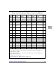
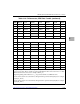
CompactPCI Connectors (P1, P2, P3, P4, P5)—
CPX8216 Standard Backplane
Primary (Front) Side I/O Connectors (Slots 1-6 and 11-16)
In the front I/O slots (system slots 1-6 and 11-16), connectors P3, P4, and
P5 are reserved for user I/O.
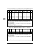
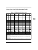
3 Ground
4 +12 Volts
Table 6-8. PWR1, PWR2, PWR3, PWR4 Pin Assignments
Pin Signal
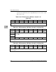
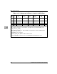
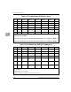
Table 6-9. SIG1, SIG2, SIG3, SIG4 Pin Assignments
Pin Signal
1 Per[n]_Pwr_ON#
2Per[n]_LED1#
3Per[n]_LED2#
4 Per[n]_PSNT_A#
5 Per[n]_PSNT_B#