
user manual


6-40 Computer Group Literature Center Web Site
Subassembly Reference
6
Primary (Front) Side CPU Connectors
The CPU connectors on the CPX8216T H.110 backplane use the same
pinouts as the CPX8216 standard backplane.
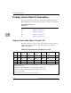
Primary (Front) Side HSC Connectors
The HSC/Bridge slot is unique. All five connectors (P5 through P1) use
standard tails, and none of the connectors pass through to the rear.
For Pinout Information
for Connector:
See:
P5 Table 6-15 on page 6-17
P4 Table 6-16 on page 6-18
P3 Table 6-17 on page 6-20
P2-Domain A Table 6-18 on page 6-20
P2-Domain B Table 6-19 on page 6-22
P1 Table 6-20 on page 6-23
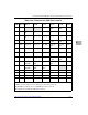
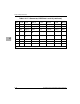
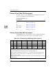
Table 6-33. P5 Connector, HSC/Bridge (Slots 8 and 10)
POS Row Z Row A Row B Row C Row D Row E Row F
25 GND _AD36 _AD35 _AD34 _AD33 _AD32 GND
24 GND _AD40 _AD39 _AD38
_GND _AD37 GND
23 GND _AD45 _AD44 _AD43 _AD42 _AD41 GND
22 GND _AD49
_+3.3 _AD48 _AD47 _AD46 GND
The _GND, _+5 and _+3 in the shaded cells are provided by the CPU board; they are not
connected to the system power plane. These signals are prefixed with CPUA if the board resides
in slot 10 or CPUB if the board resides in slot 8 (for example, CPUA_+5).
Unshaded signals beginning with an underscore (_) are prefixed with the local PCI bus name:
*For boards located in slot 10 (Domain A), the signal name is prefixed with L_PCI_A (for
example, L_PCI_A_AD17).
*For boards located in slot 8 (Domain B), the signal name is prefixed with L_PCI_B (for example,
L_PCI_B_AD17).