
user manual
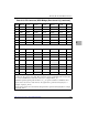
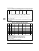
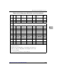

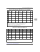

Primary (Front) Side HSC Connectors
http://www.motorola.com/computer/literature 6-43
6
17 NP NP NP NP NP NP NP
16 NP NP NP NP NP NP NP
15 NP -Vbat NP NP NP Vbat RTN NP
14-
12
KEY AREA
11 NP CT_D29 CT_D30 CT_D31 V(I/O) CT_FRAME_A# GND
10 NP CT_D27 +3.3V CT_D28 +5V CT_FRAME_B# GND
9 NP CT_D24 CT_D25 CT_D26 GND FR_COMP# GND
8 NP CT_D21 CT_D22 CT_D23 +5V CT_C8_A GND
7 NP CT_D19 +5V CT_D23 GND CT_C8_A GND
6 NP CT_D16 CT_D17 CT_D18 GND CT_NETREF_1 GND
5 NP CT_D13 CT_D14 CT_D15 +3.3V CT_NETREF_2 GND
4 NP CT_D11 +5V CT_D12 +3.3V SCLK GND
3 NP CT_D8 CT_D9 CT_D10 GND SCLK-D GND
2 NP CT_D4 CT_D5 CT_D6 CT_D7 GND GND
1 NP CT_D0 +3.3V CT_D1 CT_D2 CT_D3 GND
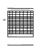
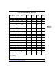
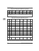
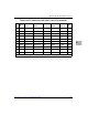
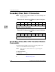
Table 6-34. P4 Connector, HSC Slots 8 and 10 (continued)
POS
Row
Z Row A Row B Row C Row D Row E
Row
F
NP=Not Populated. P4 implements the full H.110 Bus connections, which requires P4 to use
depopulated connectors.
CT_RST1# through CT_RST6# are routed radially to the bridge slots.
CT_EN1# is connected to BD_SEL1# on the backplane, and so forth.
[n]=n is the slot number.
Refer to the H.110 specifications for line terminations.