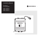
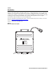
Installation Manual Broadband House Amplifier BHA-100S/P-R BHA-100K/P-R BHA-100A/P-R 101 Tournament Drive Horsham, PA 19044 POWER SUPPLY 100 - 240 VAC SERIAL NO.
IMPORTANT SAFEGUARDS 12. Power-cord Protection — Power-supply cords should be routed so 1. Read instructions — All the safety and operating instructions that they are not likely to be walked on or pinched by items placed upon or against them, paying particular attention to cords at plugs, should be read before the appliance is operated. convenience receptacles, and the point where they exit from the 2. Retain instructions — The safety and operating instructions appliance.
20. Replacement parts — When replacement parts are required, be sure the service technician has used replacement parts specified by the manufacturer or have the same characteristics may result in fire, electric shock or other hazards. 21. Safety check — Upon completion of any service or repairs to this video product, ask the service technician to perform safety checks to determine that the video product is in proper operating condition.
Special Symbols That Might Appear on the Equipment This symbol indicates that dangerous voltage levels are present within the equipment. These voltages are not insulated and may be of sufficient strength to cause serious bodily injury when touched. The symbol may also appear on schematics. The exclamation point, within an equilateral triangle, is intended to alert the user to the presence of important installation, servicing, and operating instructions in the documents accompanying the equipment.
Contents Section 1 Introduction Using this Manual ............................................................................................................................................................................ 1-2 Document Conventions................................................................................................................................................................... 1-2 If You Need Help................................................................................
ii Contents Figures Figure 1-1 BHA-100* broadband house amplifier.........................................................................................................................1-1 Figure 2-1 BHA-100* dimensions ...................................................................................................................................................2-1 Figure 2-2 BHA-100* functional block diagram .............................................................................................
Section 1 Introduction Motorola’s Broadband House Amplifier, BHA-100*, is a high performance, two-way distribution amplifier. It is designed for the sheltered environment of multiple dwelling units (MDU), such as apartment buildings, condominiums, and hospitals. The BHA-100* takes advantage of CATV technology used in extended bandwidth cable systems and is capable of two-way signal transmission with the addition of a return amplifier kit.
1-2 Introduction Using this Manual This manual contains information used to install and operate the BHA-100* amplifier. The manual is organized as follows: Section 1 Introduction provides a product description, the technical helpline, and instructions for repair/return. Section 2 Overview provides detailed information concerning BHA-100* functions and accessories. Section 3 Configuration and Installation includes instructions to configure and install the BHA-100* in the field.
Introduction 1-3 If You Need Help If you need assistance while working with the BHA-100*, contact the Motorola Technical Support Call Center (TSCC): • • • Toll Free : 1-888-944-HELP (1-888-944-4357) Direct: +1 847-725-4011or See Local Country Calling Numbers Below. Motorola Online: http://businessonline.motorola.com The TSCC is available 24 hours a day, 7 days a week.
1-4 Introduction Calling for Repairs If repair is necessary, call Motorola’s Repair Facility at 1-800-642-0442 for a Return for Service Authorization (RSA) number before sending the unit. The RSA number must be prominently displayed on all equipment cartons. The Repair Facility is open from 8:00 AM to 5:00 PM Central Time, Monday through Friday. For after hours, or international customers, a request for an RSA can be submitted via e-mail to nogrepaircenter@motorola.com.
Section 2 Overview The Motorola BHA-100* is an 1003 MHz high gain indoor distribution amplifier with a silicon power-doubled output stage. It features variable gain and slope controls and is equipped with pad and equalizer facilities for greater flexibility when adjustment is required. It uses standard Motorola accessories, including JXP-*B pads, SFE-100-* forward equalizers, SRE-100-* return equalizers, and SCS-100-* cable simulators.
2-2 Overview Several models of the BHA-100* are available to accommodate various forward and return bandpass requirements, as described in Table 2-1: Table 2-1 BHA-100* models Model Number Forward Bandpass Return Bandpass Output Stage Forward Gain BHA-100S/P-R 52 to 1003 MHz 5 to 40 MHz Power-doubled 34 dB BHA-100K/P-R 54 to 1003 MHz 5 to 42 MHz Power-doubled 34 dB BHA-100A/P-R 85 to 1003 MHz 5 to 65 MHz Power-doubled 34 dB The recommended difference in signal level between the low an
Overview 2-3 Forward Amplifier Figure 2-2 illustrates a functional block diagram of both the forward amplifier and the optional return amplifier, and applies to all models.
2-4 Overview Accessories and Options You can upgrade all models to accommodate two-way service by installing an optional return amplifier kit, model BHA-100/RA-Kit/L. This kit enables the unit to carry channels in the extended bandwidth return path. Cable equalizers and plug-in pads are also available to enhance equipment performance.
Section 3 Configuration and Installation This section provides information to configure and install the BHA-100*, including instructions to: Mount the BHA-100* Configure the BHA-100* (add accessories) Connect and supply power to the BHA-100* Adjust the output level and slope Install the return amplifier kit Mounting the BHA-100* The BHA-100* should be mounted on a flat surface and be positioned vertically. This position results in maximum air flow and the lowest operating temperature.
3-2 Configuration and Installation Figure 3-1 illustrates the BHA-100* with outer cover removed and the power supply and amplifier board covers in place. The amplifier board cover shows the location of the options and the adjustments. Figure 3-1 BHA-100* with outer cover removed 101 Tournament Drive Horsham, PA 19044 POWER SUPPLY 90 - 240 VAC SERIAL NO.
Configuration and Installation 3-3 Connecting Power Power input to the amplifier can be 90 VAC to 240 VAC. Either 50 Hz or 60 Hz is acceptable and no internal adjustments are required. The furnished line cord is terminated in an IEC 320 connector. This connector mates with power cords manufactured to meet local standards. WARNING! This equipment operates over the marked voltage and frequency range without requiring the manual setting of any selector switches.
3-4 2 Configuration and Installation Remove the equalizer jumper and replace it with the appropriate value equalizer. The location of the cable equalizer is shown in Figure 3-2. If system drawings are unavailable, use the following procedures to determine and install the appropriate equalizer. This procedure assumes normal input signal is present and the amplifier is operational.
Configuration and Installation 18 13.7 14.7 10.3 8.4 6.0 4.6 3.4 2.2 1.0 16 12.1 13.1 9.3 7.6 5.4 4.2 3.1 2.1 1.0 14 10.6 11.6 8.2 6.7 4.9 3.8 2.8 1.9 1.0 12 9.1 10.1 7.2 5.9 4.3 3.4 2.6 1.8 1.0 10 7.6 8.6 6.2 5.1 3.8 3.0 2.3 1.7 1.0 8 6.1 7.1 5.1 4.3 3.2 2.6 2.0 1.5 1.0 6 4.6 5.6 4.1 3.5 2.7 2.2 1.8 1.4 1.0 4 3.0 4.0 3.1 2.6 2.1 1.8 1.5 1.3 1.0 2 1.5 2.5 2.0 1.8 1.6 1.4 1.3 1.1 1.
3-6 Configuration and Installation Figure 3-3 shows the equalizer slope versus equalizer value information presented in Table 3-1 as a graph. The amount of cable equals the equalizer value. Figure 3-3 Equalizer slope versus cable Refer to Figure 3-3 to determine the proper cable equalizer for the BHA-100*. For example, the input tilt derived from a channel near 550 MHz and a channel at the low end of the bandpass is 6 dB. According to the graph, the appropriate (closest) equalizer is model SFE-100-8.
Configuration and Installation 3-7 Starline Cable Simulators – SCS-* The Starline Cable Simulators, Model SCS-*, are used in place of fixed equalizers in systems where the amplifiers are located close together. The simulators are designed to fit in the same location as the equalizers. Table 3-2 helps you choose the correct simulators: Table 3-2 Starline Cable Simulators SCS-* 1 2 3 4 Frequency 5 6 7 8 9 10 Cable slope in dB 40 MHz 0.1 0.1 0.1 0.1 0.2 0.2 0.3 0.3 0.3 0.4 45 MHz 0.
3-8 4 Configuration and Installation Carefully install the return hybrid gain block in the location shown in Figure 3-2. The pins of the hybrid gain block are fragile and bend when forced. 5 Fasten the component with the hardware provided to complete the hybrid gain block installation. 6 Install the SRE-* return equalizer in the location shown in Figure 3-2. 7 Install JXP-*B zero attenuation pads in the appropriate locations.
Appendix A Specifications This appendix contains tables listing general specifications for the various BHA-100* models. Refer to the on-line product catalog for current information on the BHA-100*.
Abbreviations and Acronyms The abbreviations and acronyms list contains the full spelling of the short forms used in this manual: A ampere BHA Broadband (Apartment) House Amplifier c/n carrier-to-noise CATV Community Antenna Television CSO composite second order CTB composite triple beat dB decibels dBm decibels relative to one milliwatt dBc decibels, relative to carrier level dBmV decibels relative to one millivolt FCC Federal Communications Commission IEC International Electrical Co
Visit our website at: www.motorola.