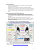
Canopy™ T1/E1 Multiplexer Application Note MUX-AN-en Issue 1 June 2005
Notices The recommendations in this Application Note and in the Canopy T1/E1 Multiplexer User Guide give the installer the knowledge to optimize the configuration settings to achieve a reliable and high performance T1/E1 link. Please refer to the Canopy System User Guide, posted at www.motorola.
Canopy T1 / E1 Application Note Issue 1, June 2005 3
Table of Contents Using This T1/E1 Multiplexer Application Note ............................................................................... 5 Searching This Application Note ..................................................................................................... 5 T1 / E1 Multiplexer Application Note ............................................................................................... 5 1.0 Abstract ..................................................................................
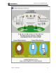
Canopy T1 / E1 Application Note Using This T1/E1 Multiplexer Application Note This document should be used with following Canopy™ User Guides*: - Canopy 45Mbps Backhaul User Guide Canopy T1/E1 Multiplexer User Guide Canopy System User Guide * Important: Visit the Canopy Support Web Site to download the latest Canopy software and Canopy User Guides. http://www.canopywireless.com/support_home.php Searching This Application Note To search this document, look in ◦ the Table of Contents for the topic.
3.0 Purpose and Goal This document describes proper setup and configuration of both Canopy backhaul elements and the TMUX devices. Additionally this document illustrates the importance of maintaining reasonable expectations for the demanding circuit emulation application over a packet infrastructure. Circuit emulation can never be as good as a “real circuit.” Traditional circuit performance metrics can only approach that of a terrestrial-based circuit from a telephony common carrier. 4.
Canopy T1 / E1 Application Note 4.
5.0 T1/E1 Multiplexer Configuration Guidelines These guidelines apply to the 20Mbps Backhaul configuration. o o o o o o o o o o o The Canopy 20Mbps Backhaul operating margin should be at least 3dB above receiver sensitivity; this is a received signal strength of better than -76dB. If Canopy 20Mbps Backhaul AES encryption (Release 7.2) is employed, be aware that doing so will drop the T1/E1 circuit once every 24 hours for the setup of a new encryption key.
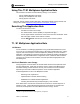
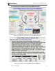
Canopy T1 / E1 Application Note Figure 4. BH20 RSSI and Jitter Display indicating no signal. In actual operation the Canopy BH20 unit will display a RSSI value above -79dBm. Motorola strongly recommends the use of passive reflectors at both ends as their narrow beam characteristic means less multipath signal and better “rejection” of whatever actual multipath signal there is. 5.
The Canopy T1/E1 Multiplexer User Guide, September 2004, section 2.4.5 correctly states the command line Ethernet configuration entry should be: Canopy port auto-negotiation is: on In section 2.5.5 for the GUI configuration of Ethernet, the same manual correctly states: Follow these steps to configure the Ethernet ports using the T1/E1 GUI Application 1. From the Main Menu, select the pull-down menu Config→Ethernet. RESULT: The Ethernet Configuration dialogue box opens. 2.
Canopy T1 / E1 Application Note Device Information 5.
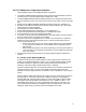
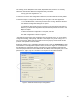
Figure 7. TMUX Length, Coding, and Clocking Configuration. 5.5 TMUX RJ45 to BNC Converter Cable If the E1 devices to the “outside” of the TMUX units does not have RJ45 (a.k.a RJ48C in the telephony industry) port capability then a “conversion cable” is needed. In this case, the E1 device has BNC 75ohm ports, on for Tx and one for Rx.
Canopy T1 / E1 Application Note There is a means of setting the converter cable’s “balun” to optionally ground (earth) the RJ45 unused pins and shield. Motorola recommends that these unused pins and shield be “grounded”, which is usually the factory default setting. This leaves the difficulty of determining the “length” of a converter cable in the sense of the TMUX configuration described in Section 5.4 above.
5.7 Jitter Following is an explanation of packet jitter: ◦ The sent packet sequence has a constant time interval between adjacent packets. ◦ The packet sequence arrives at the other TMUX with a variable time interval between the same adjacent packets. ◦ This effect, termed “packet jitter”, is introduced by the statistical nature of packet transport, in which packets are queued onto an outgoing link before being processed.
Canopy T1 / E1 Application Note In the context of T1/E1 the use of “RJ45” is widespread but probably inappropriate. The telephony industry terms this jack as a “RJ48C” even though it is physically identical. As Figure 9 illustrates the Tx and Rx pairs (often termed “tip” and “ring”) and pinouts; note they are in a crossover arrangement. Crossover means that the TX pair at one cable end becomes the Rx pair at the other cable end. Figure 9.
Additional Resources Canopy provides two additional resources: ◦ Canopy User Community at http://www.canopywireless.com/community. This resource facilitates communication with other users and with authorized Canopy experts. Available forums include General Discussion, Network Monitoring Tools, and Suggestions. ◦ Canopy Knowledge Base at http://www.canopywireless.com/kbase. This resource facilitates exploration and searches, provides recommendations, and describes tools.