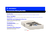
Title Communications Gateway User Guide Click your selection: Introduction Introduces your Motorola Communications Gateway and the Top and Front Panel, Connector Panel, and Battery Compartment. Before You Begin Lists the items needed to install your Motorola Communications Gateway and describes Precautions, Signing Up for Service, and Computer System Requirements.
WARNING: TO PREVENT FIRE OR SHOCK HAZARD, DO NOT EXPOSE THIS APPLIANCE TO RAIN OR MOISTURE. THE APPARATUS SHALL NOT BE EXPOSED TO DRIPPING OR SPLASHING AND NO OBJECTS FILLED WITH LIQUIDS, SUCH AS VASES, SHALL BE PLACED ON THE APPARATUS. CAUTION: TO ENSURE REGULATORY AND SAFETY COMPLIANCE, USE ONLY THE PROVIDED POWER CABLES. TO PREVENT ELECTRICAL SHOCK, DO NOT USE THIS PLUG WITH AN EXTENSION CORD, RECEPTACLE, OR OTHER OUTLET UNLESS THE BLADES CAN BE FULLY INSERTED TO PREVENT BLADE EXPOSURE.
This product is provided with a separate Regulatory and Safety Information and Software License and Warranty Information card. If one is not provided with this product, please ask your service provider or point-of-purchase representative, as the case may be. ■ THIS PRODUCT IS IN COMPLIANCE WITH ONE OR MORE OF THE STANDARDS LISTED ON THE REGULATORY AND SAFETY INFORMATION CARD. NOT ALL STANDARDS APPLY TO ALL MODELS.
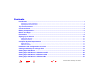
Contents Introduction ............................................................................................................................................ 1 Telephone Communications .............................................................................................................................. 1 High-Speed Internet Access .............................................................................................................................. 2 Top and Front Panel ................
Setting Up a USB Driver in Windows XP ........................................................................................... 31 Configuring TCP/IP .............................................................................................................................. 32 Configuring TCP/IP in Windows 95, 98, or Me .................................................................................. 33 Configuring TCP/IP in Windows 2000 or XP ...........................................................
Introduction Before You Begin Installation & Configuration Troubleshooting FAQ Glossary License Introduction IP telephony converges with cable data service in one convenient package! You can place your Communications Gateway on your desktop or mount the unit as described in “Wall Mounting” on page 50.
Introduction Before You Begin Installation & Configuration Troubleshooting FAQ Glossary License Introduction, continued High-Speed Internet Access Easier! Unlike dial-up modems or ISDN, you’re always on, always connected. Faster! Your Communications Gateway is up to 100 times faster than a dial-up modem. It can provide data transfer rates of up to 10 Mbps upstream and 50 Mbps downstream. Because many network and other factors can affect performance, the actual speed will vary.
Introduction Before You Begin Installation & Configuration Troubleshooting FAQ Glossary License Top and Front Panel For added security, you can press the Internet Security Lock button (1) to suspend your Internet connection. The Internet Security Lock symbol on the button lights yellow. Your computer cannot transmit or receive data. The Online light turns off until you press the Internet Security Lock button again.
Introduction Before You Begin Installation & Configuration Troubleshooting FAQ Glossary License Top and Front Panel, continued 1 Light Description 5 Battery: Off when the AC power is on and the battery is not in use (the Communications Gateway is functioning normally) ■ Solid yellow when the battery is in use (there is no AC power) ■ Flashes yellow when the battery is low ■ Solid red when the battery is missing or the battery terminals are connected backwards ■ Flashes red when the battery has fa
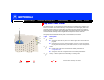
Introduction Before You Begin Installation & Configuration Troubleshooting FAQ Glossary License Connector Panel The connector panel provides cabling connectors and Ethernet status lights. Item Description 1 The standard RJ-11 telephone ports provide connections for telephone lines 1 and 2 2 When this light is on (green), the Ethernet connection is available. It blinks when data is being transferred.
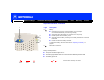
Introduction Before You Begin Installation & Configuration Troubleshooting FAQ Glossary Battery Compartment For instructions to remove the battery compartment cover, see “Cabling and Startup for a Single User” on page 13.
Introduction Before You Begin Installation & Configuration Troubleshooting FAQ Glossary License Before You Begin Before you begin the installation, check that you received the following items with your Motorola Communications Gateway: Item Description Power cord Connects to the AC electrical outlet 10/100Base-T Ethernet cable Connects to the Ethernet port USB cable Connects to the USB port Phone wire Connects a telephone line Motorola Communications Gateway CD-ROM Contains the User Guide,
Introduction Before You Begin Installation & Configuration Troubleshooting FAQ Glossary License Precautions To avoid damaging your Communications Gateway or computer with static electricity: Always make the wall connection first. Postpone Communications Gateway installation until there is no risk of thunderstorm or lightning activity in the area. To avoid damaging the Communications Gateway with static electricity: ■ Always first connect the coaxial cable to the grounded cable TV wall outlet.
Introduction Before You Begin Installation & Configuration Troubleshooting FAQ Glossary License Precautions, continued If you mount your Communications Gateway on the wall following the instructions in “Wall Mounting” on page 50, be sure that you: ■ Mount the Communications Gateway with the battery terminals facing up or sideways. To prevent possible leakage, do not mount the Communications Gateway with the battery terminals facing down.
Introduction Before You Begin Installation & Configuration Troubleshooting FAQ Glossary License Signing Up for Service To receive Internet access or telephone service, you must sign up with a cable service provider. To activate your service, call your local service provider. Cable Data Service P/N: 476203-001 Internet MAC Made in Taiwan, R.O.C.
Introduction Before You Begin Installation & Configuration Troubleshooting FAQ Glossary License Computer System Requirements You can use any web browser such as Microsoft® Internet Explorer or Netscape® Navigator® with your Motorola Communications Gateway. Your Motorola Communications Gateway is compatible with Microsoft Windows®, Macintosh®, and UNIX® computers.
Introduction Before You Begin Installation & Configuration Troubleshooting FAQ Glossary License Installation and Configuration Overview To install and configure your Motorola Communications Gateway, you need to: 1 Home Print X Exit Install the cables as described in one of: ■ “Cabling and Startup for a Single User” on page 13 ■ “Cabling for Multiple Users” on page 43 2 If you are using the USB Connection, set up the USB driver.
Introduction Before You Begin Installation & Configuration Troubleshooting FAQ Glossary License Cabling and Startup for a Single User To cable outlet or splitter Allow 5 to 30 minutes to power up the first time because the Motorola Communications Gateway must find and lock on the appropriate channels for communications. 1 Be sure your computer is on and the Communications Gateway is unplugged. 2 Connect one end of the coaxial cable to the cable outlet or splitter.
Introduction Before You Begin Installation & Configuration Troubleshooting FAQ Glossary License Cabling and Startup for a Single User, continued 3 2 6 On the battery compartment cover, push in on the tabs, as shown by arrows 1 in the illustration at top left. 7 Carefully remove the battery compartment cover by lifting up about 2 to 3 cm (1 inch) and then pulling straight out. To avoid damaging the cover, be sure you rotate it only slightly (arrow 2) before pulling it out (arrow 3).
Introduction Before You Begin Installation & Configuration Troubleshooting FAQ Glossary License Cabling and Startup for a Single User, continued 10 Plug the power cord into the Power connector on the Communications Gateway. 11 Wrap the power cord around the strain-relief posts, as shown at left. Do not plug the power cord into the AC wall outlet at this time.
Introduction Before You Begin Installation & Configuration Troubleshooting FAQ Glossary License Cabling and Startup for a Single User, continued For safety and to prevent damage to the equipment, the Communications Gateway is shipped with the battery wires disconnected. Do not short circuit the battery terminals by simultaneously touching both terminals with a metal object. 12 Connect the black negative battery wire to the black negative (-) terminal on the battery.
Introduction Before You Begin Installation & Configuration Troubleshooting FAQ Glossary License Cabling and Startup for a Single User, continued 14 On a slight angle, gently slide the top-right corner of the battery under the battery First, slide the battery under the hook hook as shown at left. While you rotate the battery into position, to avoid pinching the wires between the battery and the base, be sure the battery wires are not under the battery.
Introduction Before You Begin Installation & Configuration Troubleshooting FAQ Glossary License Cabling and Startup for a Single User, continued 17 Immediately plug the power cord into the electrical outlet. This turns your Motorola Communications Gateway on. You do not need to unplug it when not in use.
Introduction Before You Begin Installation & Configuration Troubleshooting FAQ Glossary License Cabling and Startup for a Single User, continued Caution 19 To connect the telephone line(s), plug a telephone wire into one or both phone jacks. Do not connect both the Ethernet and USB cables to the same computer. P/N : 47 62 03 - 00 1 Caution If you connect to a wired telephone wall jack, be sure it is not connected to a traditional telephone (PSTN) service. M ad e i n T ai w an , R . O. C .
Introduction Before You Begin Installation & Configuration Troubleshooting FAQ Glossary Cabling and Startup for a Single User, continued 21 Configure TCP/IP following one of: Home Print X Exit ■ “Configuring TCP/IP in Windows 95, 98, or Me” on page 33 ■ “Configuring TCP/IP in Windows 2000 or XP” on page 36 ■ The instructions in your Macintosh or UNIX user manual 20 Communications Gateway User Guide License
Introduction Before You Begin Installation & Configuration Troubleshooting FAQ Glossary License Setting Up a USB Driver The following sections describe setting up a USB driver.
Introduction Before You Begin Installation & Configuration Troubleshooting FAQ Glossary License Setting Up a USB Driver in Windows 98 SE Be sure the Motorola Communications Gateway CD-ROM is inserted in your CD-ROM drive before you plug in the USB cable. This CD contains the USB drivers and must be inserted and read by the PC before you connect the Communications Gateway to the PC. A few seconds after you complete the USB connection, the Add New Hardware Wizard window is displayed.
Introduction Before You Begin Installation & Configuration Troubleshooting FAQ Glossary License Setting Up a USB Driver in Windows 98 SE, continued 4 Be sure “CD-ROM drive” is the only box checked, as in the window at top left. 5 Click Next. If your computer successfully locates the driver, you can skip to step 8. 6 If your computer does not locate the driver, the previous window is displayed again. Select Specify a location and type the location of your CD-ROM drive as shown at bottom left.
Introduction Before You Begin Installation & Configuration Troubleshooting FAQ Glossary License Setting Up a USB Driver in Windows 98 SE, continued 8 Select The updated driver... and click Next. If this window is not displayed, verify that the Motorola Communications Gateway CD-ROM is properly inserted in the CD-ROM drive. If you still cannot find the correct driver file, click Cancel to cancel the installation and perform the procedure for “Removing the USB Driver from Windows 98 or Me” on page 57.
Introduction Before You Begin Installation & Configuration Troubleshooting FAQ Glossary License Setting Up a USB Driver in Windows 98 SE, continued After all the necessary files are loaded, the window at upper left is displayed confirming a successful installation. 10 Click Finish. The window at bottom left is displayed. 11 Click Yes to restart your computer. When you have successfully finished setting up the USB driver, you can continue with “Configuring TCP/IP in Windows 95, 98, or Me” on page 33.
Introduction Before You Begin Installation & Configuration Troubleshooting FAQ Glossary License Setting Up a USB Driver in Windows 2000 Be sure the Motorola Communications Gateway CD-ROM is inserted into the CD-ROM drive before you plug in the USB cable. A few seconds after you complete the USB connection, the Found New Hardware Wizard welcome window is displayed. 1 Click Next. 2 Be sure “Search for a suitable driver for my device” is selected. 3 Click Next.
Introduction Before You Begin Installation & Configuration Troubleshooting FAQ Glossary License Setting Up a USB Driver in Windows 2000, continued 4 Be sure “CD-ROM drives” is the only box checked, as in the window at top left. 5 Click Next. The lower window is displayed. 6 Click Next. If the Insert Disk window is displayed, be sure the Motorola Communications Gateway CD-ROM is in the CD-ROM drive and follow steps 7 to 12. Otherwise, you can skip to step 13.
Introduction Before You Begin Installation & Configuration Troubleshooting FAQ Glossary License Setting Up a USB Driver in Windows 2000, continued 7 On the Insert Disk window, click OK. The Files Needed window is displayed. 8 If necessary, select your CD-ROM drive in the Copy files from list. 9 Click Browse. 10 Locate the NetMotCM.sys file in the CD-ROM root directory. 11 Double-click the NetMotCM.sys file. The Files Needed window is displayed. 12 Click OK.
Introduction Before You Begin Installation & Configuration Troubleshooting FAQ Glossary License Setting Up a USB Driver in Windows 2000, continued 13 Click Finish to complete the installation. When you have successfully finished setting up the USB driver, you can continue with “Configuring TCP/IP in Windows 2000 or XP” on page 36. If you have any difficulties setting up the USB driver, follow the instructions for “Removing the USB Driver from Windows 2000 or XP” on page 61.
Introduction Before You Begin Installation & Configuration Troubleshooting FAQ Glossary License Setting Up a USB Driver in Windows Me Be sure the Motorola Communications Gateway CD-ROM is inserted into the CD-ROM drive before you plug in the USB cable. A few seconds after you complete the USB connection, the Add New Hardware Wizard window is displayed. 1 Click Next. Windows Me automatically searches for the correct USB drivers and installs them.
Introduction Before You Begin Installation & Configuration Troubleshooting FAQ Glossary License Setting Up a USB Driver in Windows XP Be sure the Motorola Communications Gateway CD-ROM is inserted into the CD-ROM drive before you plug in the USB cable. A few seconds after you complete the USB connection, the Found New Hardware Wizard window is displayed. 1 Be sure “Install the software automatically” is selected. 2 Click Next.
Introduction Before You Begin Installation & Configuration Troubleshooting FAQ Glossary License Configuring TCP/IP The Motorola Communications Gateway contains all required software. You do not need to configure the Communications Gateway, but you must configure your computer for TCP/IP (a protocol for communication between computers) and check for an IP address. Your service provider may provide additional instructions to set up your computer.
Introduction Before You Begin Installation & Configuration Troubleshooting FAQ Glossary License Configuring TCP/IP in Windows 95, 98, or Me The following instructions are for Windows 95, 98 and Me. For Windows 2000 or XP, see “Configuring TCP/IP in Windows 2000 or XP” on page 36. For a Macintosh or UNIX system, refer to your user guide. 1 On the Windows Desktop, click Start. 2 Select Settings and then Control Panel from the pop-up menus.
Introduction Before You Begin Installation & Configuration Troubleshooting FAQ Glossary License Configuring TCP/IP in Windows 95, 98, or Me, continued Home Print X Exit 6 Click Add. 7 Double-click the Protocol option on Select Network Component Type window. 8 Click Microsoft in the Manufacturers section and click TCP/IP in the Network Protocol section of Select Network Protocol window. 9 Click OK.
Introduction Before You Begin Installation & Configuration Troubleshooting FAQ Glossary License Configuring TCP/IP in Windows 95, 98, or Me, continued 10 Click TCP/IP on the Network window. If there is more than one TCP/IP entry, choose the one for the Ethernet card or USB port connected to the Communications Gateway. 11 Click Properties. The TCP/IP window is displayed. 12 Click the IP Address tab. 13 Click Obtain an IP address automatically. 14 Click OK to accept the TCP/IP settings.
Introduction Before You Begin Installation & Configuration Troubleshooting FAQ Glossary License Configuring TCP/IP in Windows 2000 or XP The following instructions are for Windows 2000 or XP. For Windows 95, 98, or Me, see “Configuring TCP/IP in Windows 95, 98, or Me” on page 33. For a Macintosh or UNIX system, refer to your user guide. Home Print X Exit 1 On the Windows Desktop, click Start. 2 Select Settings and then Control Panel from the pop-up menus.
Introduction Before You Begin Installation & Configuration Troubleshooting FAQ Glossary License Configuring TCP/IP in Windows 2000 or XP, continued 5 Click Properties. Information similar to the lower window is displayed. 6 If Internet Protocol (TCP/IP) is in the list of components, TCP/IP is installed. You can skip to step 10. If Internet Protocol (TCP/IP) is not in the list, click Install. The Select Network Component Type window is displayed. Continue with step 7.
Introduction Before You Begin Installation & Configuration Troubleshooting FAQ Glossary License Configuring TCP/IP in Windows 2000 or XP, continued Home Print X Exit 7 Click Protocol on the Select Network Component Type window and click Add. The Select Network Protocol window is displayed. 8 Click Internet Protocol (TCP/IP) in the Network Protocol section on the Select Network Protocol window. 9 Click OK. The Local Area Connection number Properties window is re-displayed.
Introduction Before You Begin Installation & Configuration Troubleshooting FAQ Glossary License Configuring TCP/IP in Windows 2000 or XP, continued 10 On the Local Area Connection number Properties window, be sure the box next to Internet Protocol (TCP/IP) is checked. 11 Click Properties. The Internet Protocol (TCP/IP) Properties window is displayed as shown at bottom left. 12 Be sure Obtain IP address automatically and Obtain DNS server address automatically are selected.
Introduction Before You Begin Installation & Configuration Troubleshooting FAQ Glossary License Verifying the IP Address in Windows 95, 98, or Me The following instructions are for Windows 95, 98, or Me. For information about Windows 2000 or XP, see “Verifying the IP Address in Windows 2000 or XP” on page 41. For a Macintosh or UNIX system, refer to your user guide.
Introduction Before You Begin Installation & Configuration Troubleshooting FAQ Glossary License Verifying the IP Address in Windows 2000 or XP The following instructions are for Windows 2000 or Windows XP. For information about Windows 95, 98, or Me, see “Verifying the IP Address in Windows 95, 98, or Me” on page 40. For a Macintosh or UNIX system, refer to your user guide. To check the IP address: 1 On the Windows Desktop, click Start. 2 Select Run. The Run window is displayed.
Introduction Before You Begin Installation & Configuration Troubleshooting FAQ Glossary License Verifying the IP Address in Windows 2000 or XP, continued To renew your IP address: 1 Type ipconfig /renew and press ENTER. If a valid IP address is displayed as shown at left, Internet access should be available. 2 Type exit and press ENTER to return to Windows. If after performing this procedure your computer cannot access the Internet, call your service provider for help.
Introduction Before You Begin Installation & Configuration Troubleshooting FAQ Glossary License Cabling for Multiple Users Cable outlet Coaxial cable Motorola Communications Gateway USB cable For information about multiple user service, contact your service provider. Ethernet cable Computer Computer Do not connect both the Ethernet and USB cables to the same computer.
Introduction Before You Begin Installation & Configuration Troubleshooting FAQ Glossary License Cabling for Multiple Users, continued Ethernet Cable outlet Coaxial cable You can connect up to 32 computers to an Ethernet hub connected to a Motorola Communications Gateway, as shown at left. For an overview of the installation process, see “Installation and Configuration Overview” on page 12.
Introduction Before You Begin Installation & Configuration Troubleshooting FAQ Glossary License Replacing the Battery When the the battery: battery light on the Top and Front Panel does any of the following, replace ■ Flashes yellow — the battery is low ■ Flashes red — the battery has failed ■ Lights solid red — the battery is missing Caution Replacing the battery with an incorrect type can cause an explosion. Use a CSB GP 1222 F2 12V 2.2 Ah battery only.
Introduction Before You Begin Installation & Configuration Troubleshooting FAQ Glossary License Replacing the Battery, continued Battery hook 2 For a description of the battery compartment, see “Battery Compartment” on page 6. 4 As shown at top left, depress both battery snaps (arrows 1) while gently raising the positive end of the battery (arrow 2). 5 When the battery rotates past the snaps, slide the battery out as shown at lower left.
Introduction Before You Begin Installation & Configuration Troubleshooting FAQ Glossary License Replacing the Battery, continued Home Print X Exit 6 Carefully remove the wires from the old battery terminals. 7 Recycle the battery according to the instructions on the battery or contact your service provider for information. 8 On the new battery, connect the black negative battery wire to the black negative (-) terminal.
Introduction Before You Begin Installation & Configuration Troubleshooting FAQ Glossary License Replacing the Battery, continued 10 On a slight angle, gently slide the top-right corner of the battery under the battery First, slide the battery under the hook hook as shown at left. While you rotate the battery into position, to avoid pinching the wires between the battery and the base, be sure the battery wires are not under the battery.
Introduction Before You Begin Installation & Configuration Troubleshooting FAQ Glossary License Replacing the Battery, continued 13 Plug the power cord into the electrical outlet. To confirm normal operation of the Communications Gateway, check that the battery light on the Top and Front Panel is off. To test that the battery is connected and working normally, briefly unplug the power cord. If the battery is connected and providing backup power, the battery light turns solid yellow.
Introduction Before You Begin Installation & Configuration Troubleshooting FAQ Glossary License Wall Mounting If you mount the Communications Gateway on the wall, you must: ■ Locate the unit as specified by the local or national codes governing residential or business cable TV and communications services. ■ Follow all local standards for installing a Network Interface Unit/Network Interface Device (NIU/NID). ■ Mount the Communications Gateway with the battery terminals facing up or sideways.
Introduction Before You Begin Installation & Configuration Troubleshooting FAQ Glossary License Wall Mounting, continued To mount your Communications Gateway on the wall: 1 Print the Wall Mounting Template on page 53: Click the Print icon or choose Print from the File menu to display the Print dialog box. (The example at left is from Adobe® Acrobat® Reader® running on Windows 2000; there may be slight differences in your version.) Be sure you print the template at 100% scale.
Introduction Before You Begin Installation & Configuration Troubleshooting FAQ Glossary License Wall Mounting, continued 6 If necessary, seat an anchor in each hole. Use M5 x 38 mm (#10-16 x 11/2 inch) screws with a flat underside and maximum screw head diameter of 10.5 mm to mount the Communications Gateway. 7 7.6 mm maximum 10.5 mm maximum 4.0 mm Home Print X Exit Using a screwdriver, turn each screw until part of it protrudes from the wall, as shown at left: ■ There must be 4.
Introduction Before You Begin Installation & Configuration Troubleshooting FAQ Glossary License Wall Mounting Template You can print this page to use as a wall mounting template. Be sure you print it at 100% scale. (In Acrobat reader, be sure that Fit To Page is not checked in the Print dialog box.) Measure the printed template with a ruler to ensure that it is the correct size. 125.0 mm (4.
Introduction Before You Begin Installation & Configuration Troubleshooting FAQ Glossary License Troubleshooting If the solutions listed here do not solve your problem, contact your service provider. Before calling your service provider, try pressing the reset button on the rear panel. Resetting the Communications Gateway may take 5 to 30 minutes. Your service provider may ask for the status of the lights as described in “Lights and Error Conditions” on page 56.
Introduction Before You Begin Installation & Configuration Troubleshooting FAQ Glossary License Problem Possible Solutions Cannot send or receive data Check the lights. Note the first light from top to bottom that is off. This light indicates where the error occurred as described in “Lights and Error Conditions” on page 56. If the Internet Security Lock light is on, your computer cannot transmit or receive data. Press the Internet Security Lock button to reconnect your Internet service.
Introduction Before You Begin Installation & Configuration Troubleshooting FAQ Glossary Lights and Error Conditions Light During Startup During Normal Operation Battery Lights solid yellow when the battery is connected and charged and the AC power is disconnected Flashes yellow if the battery is low Flashes red if the battery is missing Lights solid yellow when the battery is connected and charged and there is no AC power Flashes yellow if the battery is low Flashes red if the battery is missing
Introduction Before You Begin Installation & Configuration Troubleshooting FAQ Glossary License Troubleshooting, continued Removing the USB Driver from Windows 98 or Me 1 On your Windows Desktop, right-click the Network Neighborhood icon and select Properties. The Network window is displayed. 2 In the list of installed network components, select the Motorola Communications Gateway. For example, the image at left shows a CG5500.
Introduction Before You Begin Installation & Configuration Troubleshooting FAQ Glossary License Troubleshooting, continued Home Print X Exit 3 Click Remove. The Network window no longer displays a Motorola Communications Gateway in the list. 4 Click OK. The System Settings Change window is displayed. 5 Click Yes to restart your computer. After your computer restarts, continue with step 6.
Introduction Before You Begin Installation & Configuration Troubleshooting FAQ Glossary License Troubleshooting, continued 6 Insert the Motorola Communications Gateway CD-ROM in the CD-ROM drive. After a short time, a window with language choices is displayed. 7 Press the Esc key on the keyboard to exit the start-up screens. 8 To start Windows Explorer, click Start and select Run. 9 In the Run window, type explorer and click OK. The Exploring window is displayed.
Introduction Before You Begin Installation & Configuration Troubleshooting FAQ Glossary Troubleshooting, continued 15 Click Remove Driver to remove the USB driver. After you remove the USB driver, re-install the USB driver following one of: ■ “Setting Up a USB Driver in Windows 98 SE” on page 22 ■ “Setting Up a USB Driver in Windows Me” on page 30 If you continue to have problems, contact your service provider.
Introduction Before You Begin Installation & Configuration Troubleshooting FAQ Glossary License Troubleshooting, continued Removing the USB Driver from Windows 2000 or XP 1 For Windows XP, skip to step 13. For Windows 2000, on your desktop, click Start. Home Print X Exit 2 Click Settings. 3 Click the Control Panel icon. The Control Panel window is displayed. 4 Double-click the Add/Remove Hardware icon to start the Add/Remove Hardware Wizard.
Introduction Before You Begin Installation & Configuration Troubleshooting FAQ Glossary Troubleshooting, continued Home Print X Exit 5 Click Next. The Choose a Hardware Task window is displayed. 6 Select Uninstall/Unplug a device and click Next.
Introduction Before You Begin Installation & Configuration Troubleshooting FAQ Glossary License Troubleshooting, continued 7 Select Uninstall a device and click Next. The Installed Devices on Your Computer window is displayed. If you unplugged the USB cable from the Communications Gateway and the Unsafe Removal of a Device window was displayed, the Communications Gateway probably is not listed as shown in the lower window. 8 Be sure “Show hidden devices” is selected (checked).
Introduction Before You Begin Installation & Configuration Troubleshooting FAQ Glossary License Troubleshooting, continued 10 On the window at top left, select Yes, I want to uninstall this device and click Next. 11 On the lower window, click Finish. 12 Close the Control Panel window.
Introduction Before You Begin Installation & Configuration Troubleshooting FAQ Glossary License Troubleshooting, continued 13 Insert the Motorola Communications Gateway CD-ROM in the CD-ROM drive. After a short time, a window with language choices is displayed. 14 Press the Esc key on the keyboard to exit the start-up screens. 15 To start Windows Explorer, click Start and select Run. 16 In the Run window, type explorer and click OK. The Exploring window is displayed.
Introduction Before You Begin Installation & Configuration Troubleshooting FAQ Glossary License Troubleshooting, continued 22 Click Remove Driver. Informational messages similar to the ones shown at left are displayed on the Motorola USB Driver Removal Utility window. If a window similar to the following is displayed, click OK. You can ignore the error message.
Introduction Before You Begin Installation & Configuration Troubleshooting FAQ Glossary License Contact Us For information about customer service, technical support, or warranty claims, see the Software License and Warranty Information card provided with your Motorola Communications Gateway. For answers to typical questions, see “Frequently Asked Questions” on page 68. For information about Motorola consumer cable products, education, and support, visit http://www.motorola.com/broadband.
Introduction Before You Begin Installation & Configuration Troubleshooting FAQ Glossary License Frequently Asked Questions Here are answers to questions our customers frequently ask. Q What is high-speed cable Internet access? A Cable Internet access uses cable television wires instead of telephone lines to connect to the Internet. It is extremely fast and affordable and does not tie up telephone lines for incoming or outgoing calls and faxes.
Introduction Before You Begin Installation & Configuration Troubleshooting FAQ Glossary License Q What are CableLabs Certified, DOCSIS and EuroDOCSIS? A CableLabs® Certified™, DOCSIS™, and EuroDOCSIS™ are the industry standards for high-speed data distribution over cable television system networks. They are intended to ensure that all compliant cable modems and Communications Gateways interface with all compliant cable systems.
Introduction Before You Begin Installation & Configuration Troubleshooting FAQ Glossary License Q Do I need to subscribe to cable TV to get cable Internet access or phone service? A No, but you need to subscribe to cable Internet or phone service. Some systems require you to subscribe to basic service to get Internet or phone access. Check with your cable company for specific information.
Introduction Before You Begin Installation & Configuration Troubleshooting FAQ Glossary License Glossary coaxial cable (coax) A type of wire consisting of a center wire surrounded by insulation and a grounded shield of braided wire. The shield minimizes electrical and radio frequency interference. configuration data The data the Communications Gateway downloads from servers specified by your service provider.
Introduction Before You Begin Installation & Configuration Troubleshooting FAQ Glossary License Ethernet The most widely used type of local area network (LAN). The most commonly installed Ethernet networks are called 10Base-T. 10Base-T provides transmission speeds up to 10 megabits per second (Mbps), usually over twisted-pair wire. Fast Ethernet (100Base-T) provides transmission speeds up to 100 Mbps.
Introduction Before You Begin Installation & Configuration Troubleshooting FAQ Glossary License splitter A splitter is a device that divides the signal power from an input cable equally between two or more signals, each carrying a selected frequency range. The Motorola Communications Gateway requires a 5-900 MHz RF splitter to connect to a cable outlet that is also used for a TV.
Introduction VoIP Before You Begin Installation & Configuration Troubleshooting FAQ Glossary License Voice over Internet Protocol is a method to exchange voice, fax, and other information over the Internet. Voice and fax have traditionally been carried over traditional telephone lines using a dedicated circuit for each line. VoIP enables calls to travel as discrete data packets on shared lines.
Software License Motorola Communications Gateways Motorola, Inc., Broadband Communications Sector (“Motorola”) Cable Data/Telephony Division 101 Tournament Drive Horsham, PA 19044 IMPORTANT: PLEASE READ THIS SOFTWARE LICENSE (“LICENSE”) CAREFULLY BEFORE YOU INSTALL, DOWNLOAD OR USE ANY APPLICATION SOFTWARE, USB DRIVER SOFTWARE, FIRMWARE AND RELATED DOCUMENTATION (“SOFTWARE”) PROVIDED WITH MOTOROLA’S TELEPHONY COMMUNICATIONS GATEWAY PRODUCT (THE “CG PRODUCT”).
You may not: (1) Loan, distribute, rent, lease, give, sublicense or otherwise transfer the Software, in whole or in part, to any other person, except as permitted under the TRANSFER paragraph above. (2) Copy or translate the User Guide included with the Software, other than for personal use. (3) Copy, alter, translate, decompile, disassemble or reverse engineer the Software, including but not limited to, modifying the Software to make it operate on non-compatible hardware.
493049-001 3/02 English MGBI