
user manual


Installation Instructions
MVME162IG/D2 2-11
2
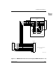
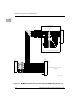
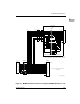
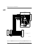
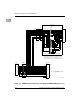
8. Connect the P2 Adapter Board or LCP2 Adapter Board and cable(s) to
MVME162 backplane connector P2. This provides a connection point for
terminals or other peripherals at the EIA-232-D serial ports, SCSI ports,
and LAN Ethernet port.
For information on installing the P2 or LCP2 Adapter Board and the
MVME712 series transition module(s), refer to the manuals listed in
Related Documentation in Chapter 1 (the MVME162 Embedded Controller
Programmer’s Reference Guide provides some connection diagrams.)
9. Connect the appropriate cable(s) to the panel connectors for the EIA-232-
D serial ports, SCSI port, and LAN Ethernet port.
– Note that some cables are not provided with the MVME712 series
module and must be made or purchased by the user. (Motorola
recommends shielded cable for all peripheral connections to minimize
radiation.)
10. Connect the peripheral(s) to the cable(s). Appendix A supplies detailed
information on the EIA-232-D signals supported. Appendix B describes
the Ethernet LAN (Local Area Network) port connections. Appendix C
describes the SCSI (Small Computer System Interface) I/O bus connections.
11. Install any other required VMEmodules in the system.
12. Replace the chassis cover.
13. Connect the power cable to the AC power source and turn the equipment
power ON.
System Considerations
The MVME162 draws power from VMEbus backplane connectors P1 and P2.
P2 is also used for the upper 16 bits of data in 32-bit transfers, and for the upper
8 address lines used in extended addressing mode. The MVME162 may not
function properly without its main board connected to VMEbus backplane
connectors P1 and P2.
Whether MVME162 operates as VMEbus master or VMEbus slave, it is
configured for 32 bits of address and 32 bits of data (A32/D32). However, it
handles A16 or A24 devices in the address ranges indicated in Chapter 1. D8
and/or D16 devices in the system must be handled by the MC68040/
MC68LC040 software. Refer to the memory maps in the MVME162 Embedded
Controller Programmer’s Reference Guide.)
The MVME162 contains shared onboard DRAM whose base address is
software-selectable. Both the onboard processor and offboard VMEbus
devices see this local DRAM at base physical address $00000000, as