
Laptop User Manual


Port Configuration Transition Module Preparation and Installation
CPCI-6020 CompactPCI Single Board Computer Installation and Use (6806800A51C)
135
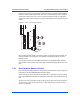
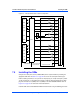
7.4.4 Port Configuration
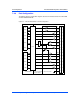
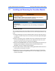
The following interface configuration diagrams describe the interface between the CPCI-6020
and CPCI-6020-MCPTM-01.
Figure 7-5 EIA-232-D DCE Ports 3 and 4 Configuration
TXD
RTS#
RXD
CTS#
RTXC
TRXC
EIA-232-D DCE SIM
DSR#
DTR#
LLB#
RLB#
DCD#
RI#
TM#
7
24
21
20
19
17
6
2
4
1
14
3
16
23
5
Z85230 SCC
Z8536 CIO
HD-26
J3/MX
RXD
CTS#
TXD
RTS#
DTR#
TXC
RXC#
ETXC
DCD#
TM#
RI#
DSR#
RL
LL
GND
J17, J16
3
2
1
Transition Module
CPCI-6020-MCPTM-01
CPCI-6020
COM3 COM4
J1 J1
27
29
26
28
44
39
41
48
32
49
46
30
45
42
31